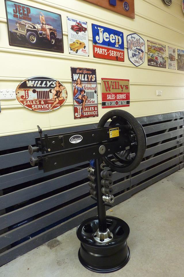
Eastwood 27" Bead Roller Modifications.
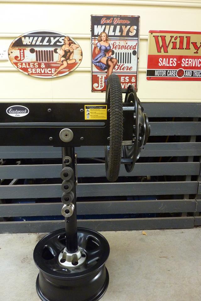
Made a stand for my new 27" bead roller. This is too heavy to always be lifting up into a vice to use so thought this would be better. Cost me nothing as well. Old Jeep wheel along with a pipe I pulled from the ground in a vacant lot and the bar stock from an old shopping trolley! To make it easier to use I changed from a crank handle to a wheel setup. But also moved it across to the end of the slot which is 200mm/8" closer than the crank handle. Easier to see and guide the work when you are not so stretched out. I couldn't find a big steering wheel or a tube ring so grabbed a 20" BMX wheel that was being thrown out. Works really well with a comfortable grip.
So the upper shaft comes up which you unwind to get the work piece out, I simply looped an extension spring around it hooked onto a rod that passed through holes drilled in the side plates. Rod came from a spear end! Whipped up a little stainless tray from some scrap.
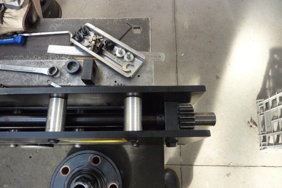
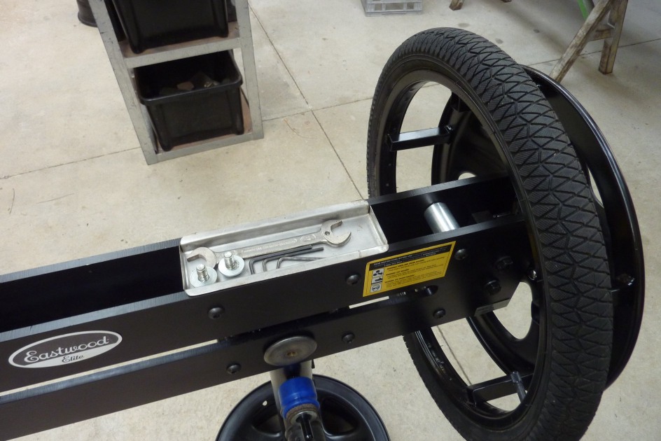
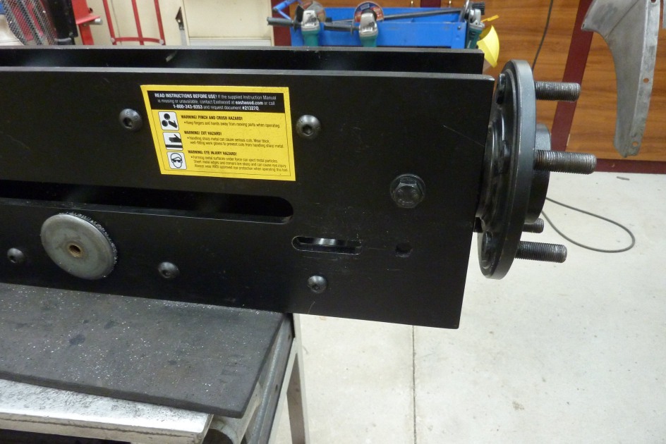
Looking at the way rollers' gear and support blocks are setup. I thought maybe I could get more depth from the shafts with an easy change. Notice the gear is behind the support block with the collar and set screw on the other side. I simply swapped the gear with the collar and slid the shaft through further. The position change has the shaft 2" further out from the end of the frame now turning this 27" roller into a 29" one.
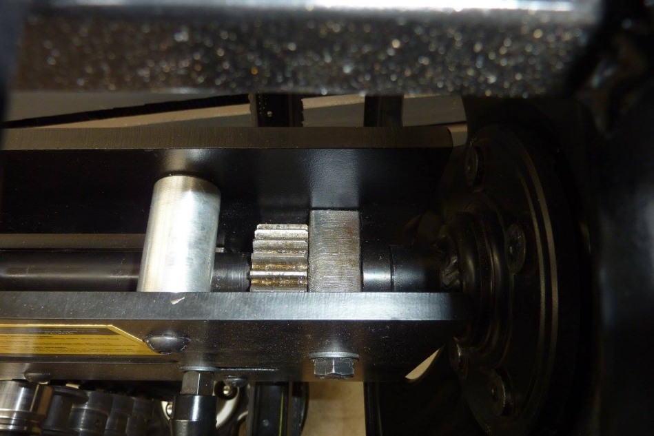
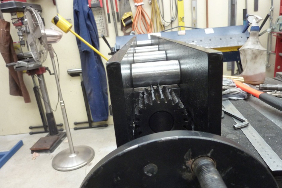
I wanted more adjustment and an easier way of adjusting a shaft back and forth to line up different profile combinations etc. Took the gear from the top shaft and added it to the bottom one as a matched pair. Then grabbed another gear to put back on the top shaft from my old 24" roller. Same number of teeth etc but wanted to match the bottoms ones perfectly. Remember that the bolt still in place holds the support block and has the gear sitting in front of it. The bottom shaft has both gears behind the block so it had to be moved forward to sit under the new upper gear position. This will be slotted to allow adjustment under the fixed upper.
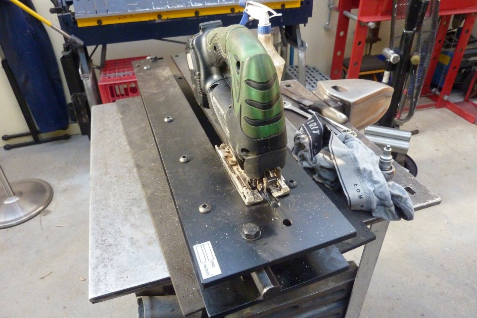
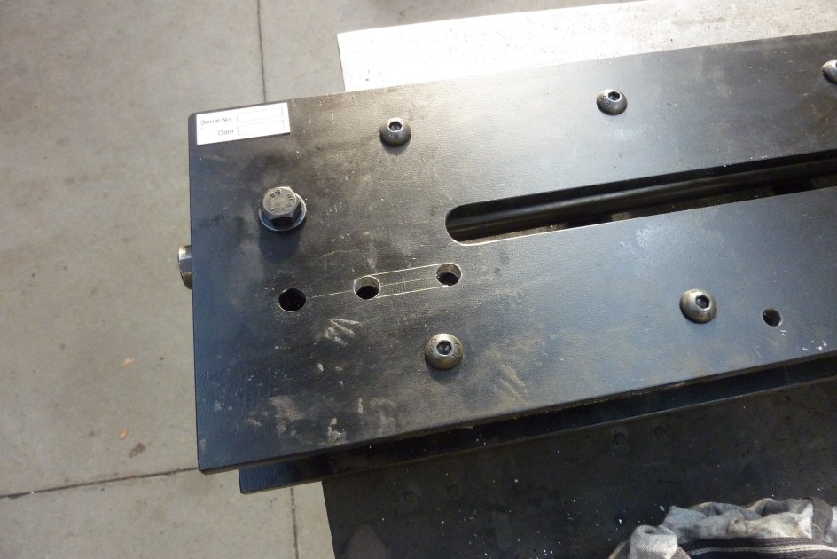
I cut in between the holes with a thin cutoff wheel first and then cut the rest through with a fine metal blade jigsaw. Used lanolin as a lubricant. Almost looks milled after some hand filing.
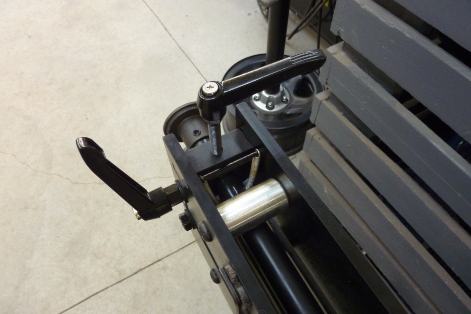
Stopping the full range of adjustment on the lower shaft (frame is upside down) was this round frame bar. Rather than weaken it by grinding out a radius in the bar, I'll just drill another set of holes above it and move it out of the way. Can see the new set of holes ready for the bar to go back in out of the way.
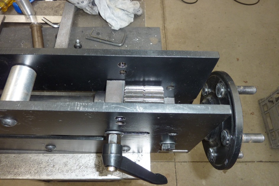
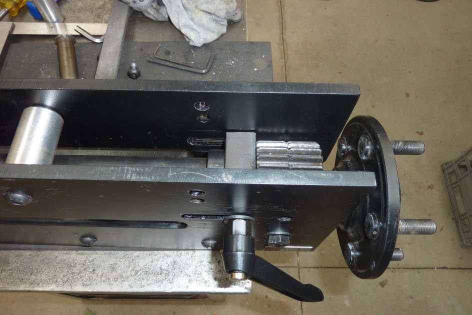
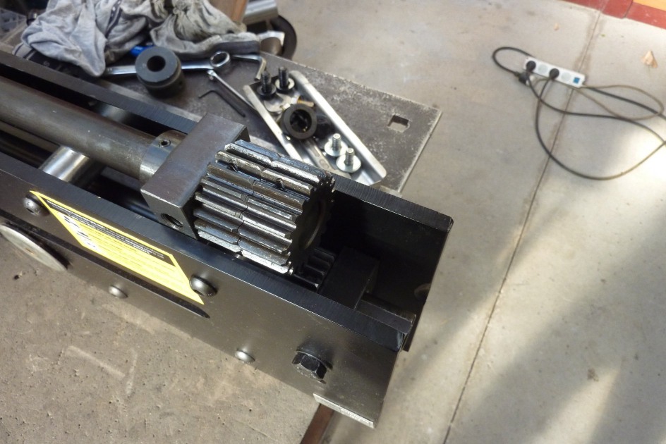
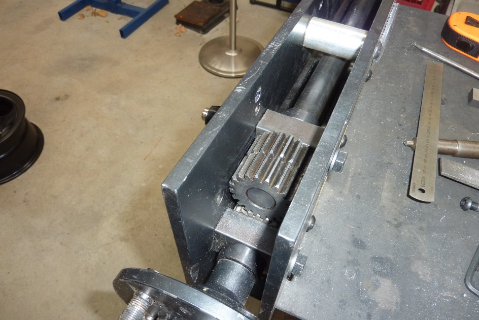
Before the bar goes back in it might be a good time to show the adjustment. I took the handle from the front support block to use here. The bolt on the other side is just finger tight to allow it to slide in the slot when this side it not locked tight. With the frame still upside down, the fixed gear that engages with the ones shown is directly under the rear of the two gears. So this is the full forward position. Now the shaft with the collar, support block and two gears, all move together back 40mm/1.5" approx. until the front gear is over the other one.
[INDEX]