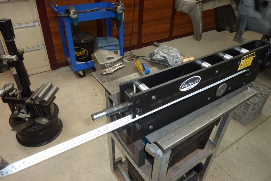
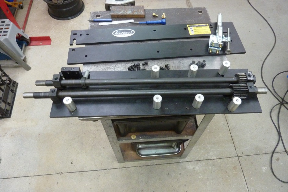
Round frame bar bolted back in with plenty of clearance with the gears. So the end fixed top bar now measures 29" instead of 27". I can adjust out to even 30" by just altering the set screws but that distance away from the support blocks is going to allow flex in the end of the shaft. I still have the option of loosening the set screws on the gear and collar and moving this back shorter when doing thicker sheet and don't need the extra depth. Extending the frame and moving the supports forward is another option. I'll see what is needed as I use it more.
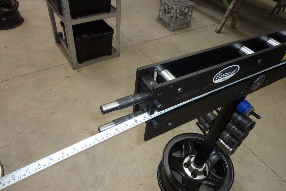
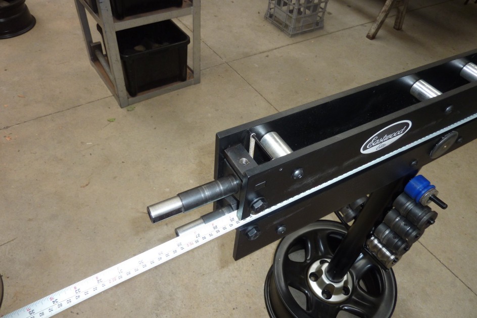
Bottom shaft forward is nearly 29.5". Bottom shaft all the way back is 27.75"
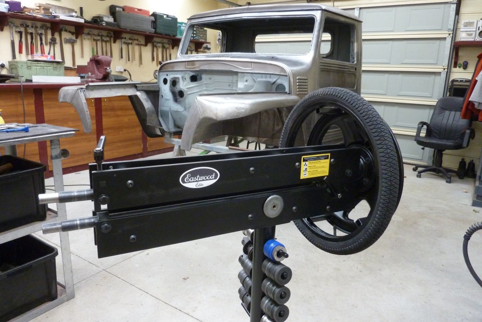
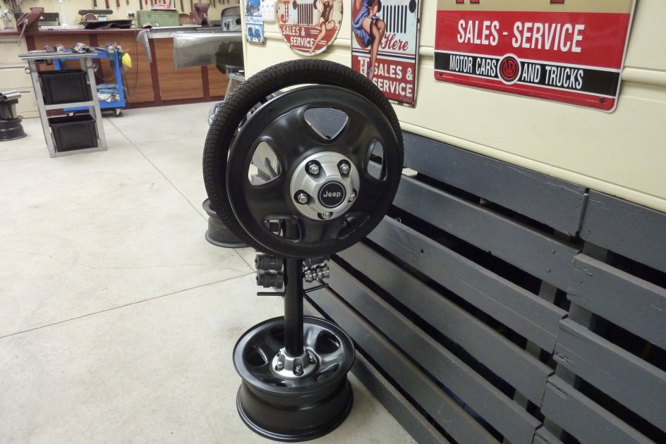
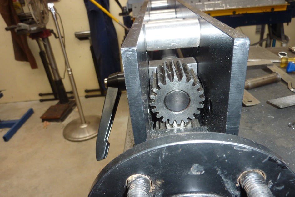
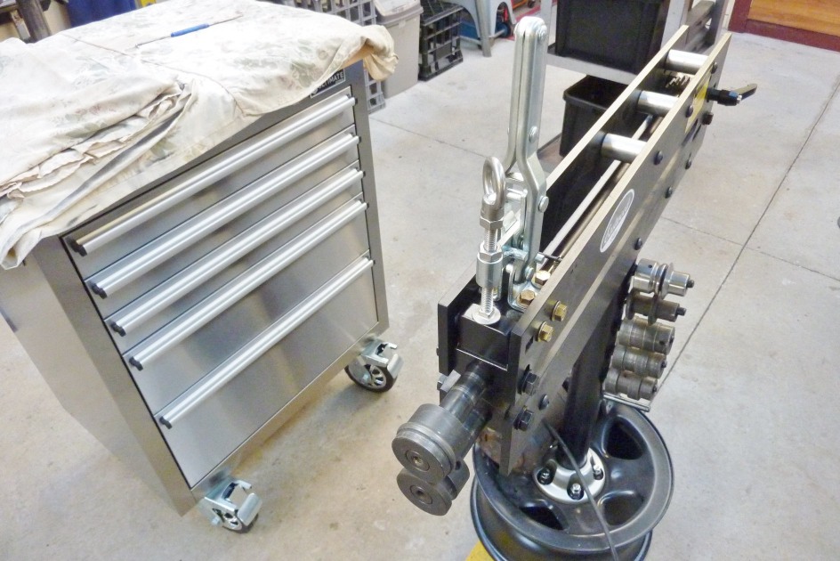
Personal preference if you prefer the top or bottom shaft adjustable. The driven shaft is better stationary. As this is still hand driven I prefer the top shaft to have the wheel as it is easier to pull on the wheel when feeding the metal in than push it forward. Think I would switch it the other way if I had a motor attached as you don't want that to be the tilting one. Stock comes that way around. Even added the hub cap on the top and wheel studs holding the complete bearing hub underneath. The extra weight low down helps with balance as well.
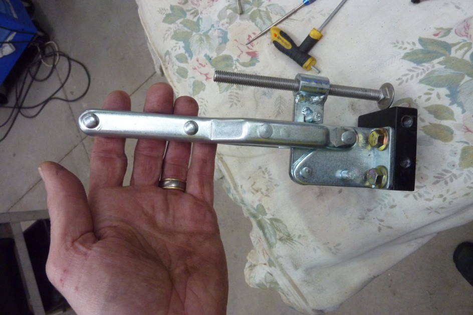
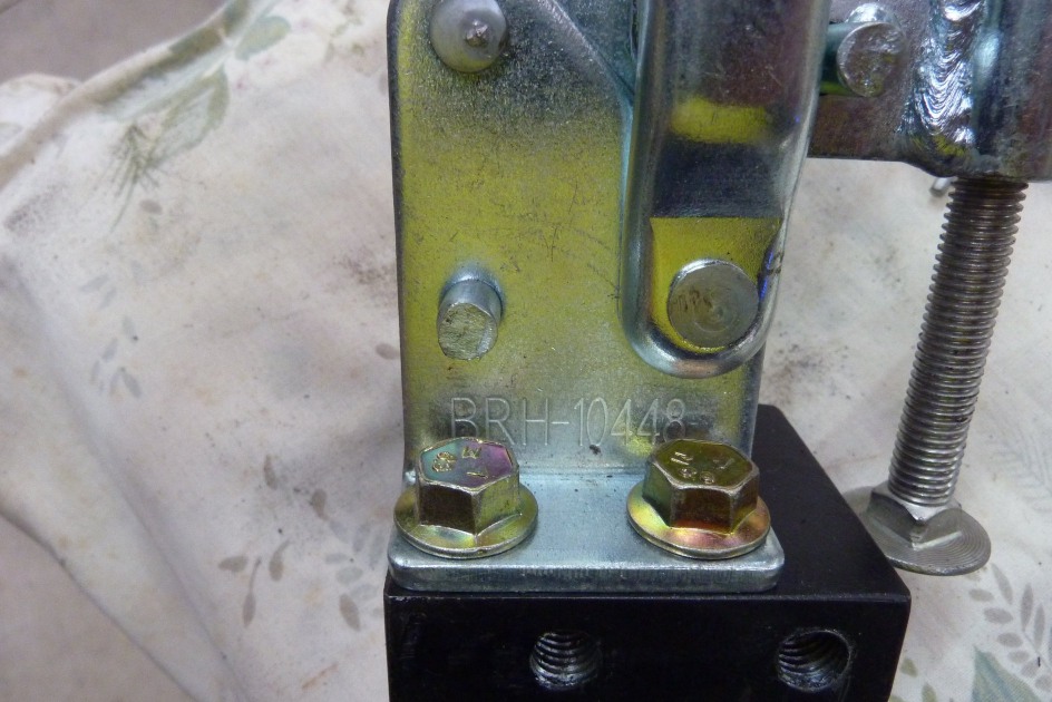
Did a lot of searching to find a easy simple way to have a quick release on the upper tension screw. I wanted one with a high load rating that at least matched the standard tension screw diameter to make sure it met the pressure and deflection requirements. I came up with this vertical toggle clamp that has the matching M10 hold down screw. Has a 400kg pressure capacity and the model is BRH-10448.
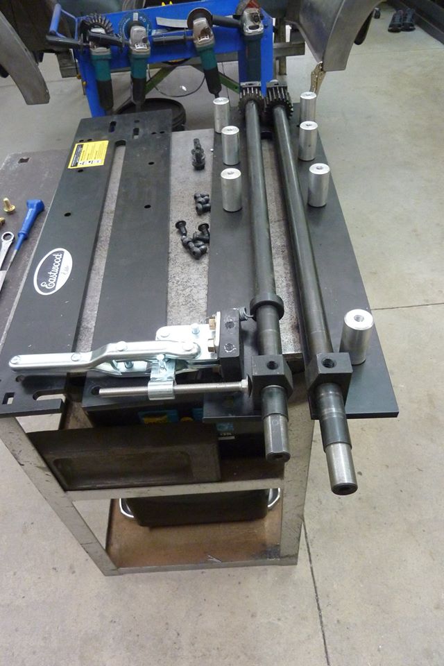
I replaced one of the spacer bars with a 19mm-3/4" plate that I could drill and tap. Important to offset the mounting holes so they don't run into each other. I was able to use the existing hole from the old bar and just added one more. I wanted the mount to be as close as possible to the upper shaft at its fully raised position to reduce the arc the toggle works at. I swapped the supplied hold down bolt with a stainless steel coach bolt to increase the ease of the engagement under pressure. This is important, and the main reason for the conversion, that when doing repeated lines in a piece of work and you need to reposition each time to run the next one at exactly the same pressure. No more remembering how many turns up and down each time.
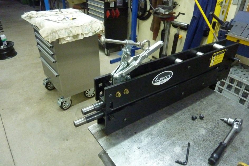
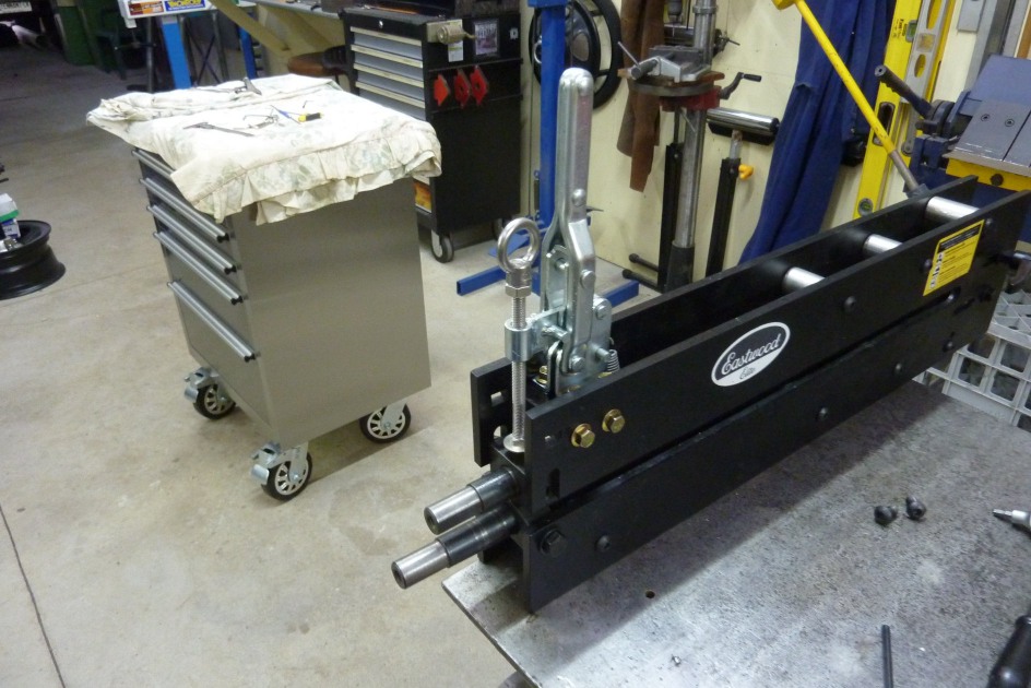
It releases up higher than needed, but that can be altered by raising the stop pin if wanted. You will also note that I added a stainless eyebolt head to the top for adjustment. This is where some of the other straight sliding toggle clamps were let down with the ease you could adjust the bolt when under pressure especially.
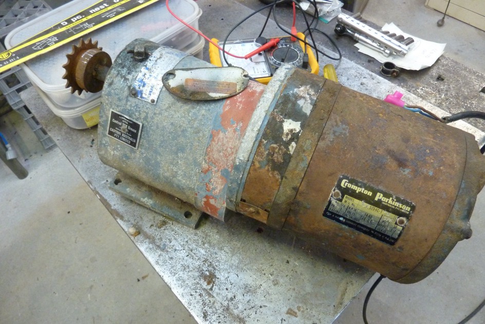
To reduce the arc that the head of the adjustment bolt hits the pillow block, I just welded on a block of 19mm-3/4" plate to the top of it. There is no play in the toggle clamp and even needs to be oiled as instructed to work it by hand to start with. There was however a little play in the threaded boss, but adding a nut above it removed this and only needs to be finger tight. I have since swapped it for a wing nut which also means you can lock the adjustment if doing a lot of work that needs repeatability. Found this old motor and gearbox under my Dads house when we were clearing it out. I wired a temporary lead to it and it still ran! It was a Crompton and Parkinson single phase induction motor, 1/4hp, 1440 rpm, 1.7 amps, 240 A/C, Continuous rated motor. Gearbox slowed it down to a very slow 1.7 rpm according to the plate!
[INDEX]