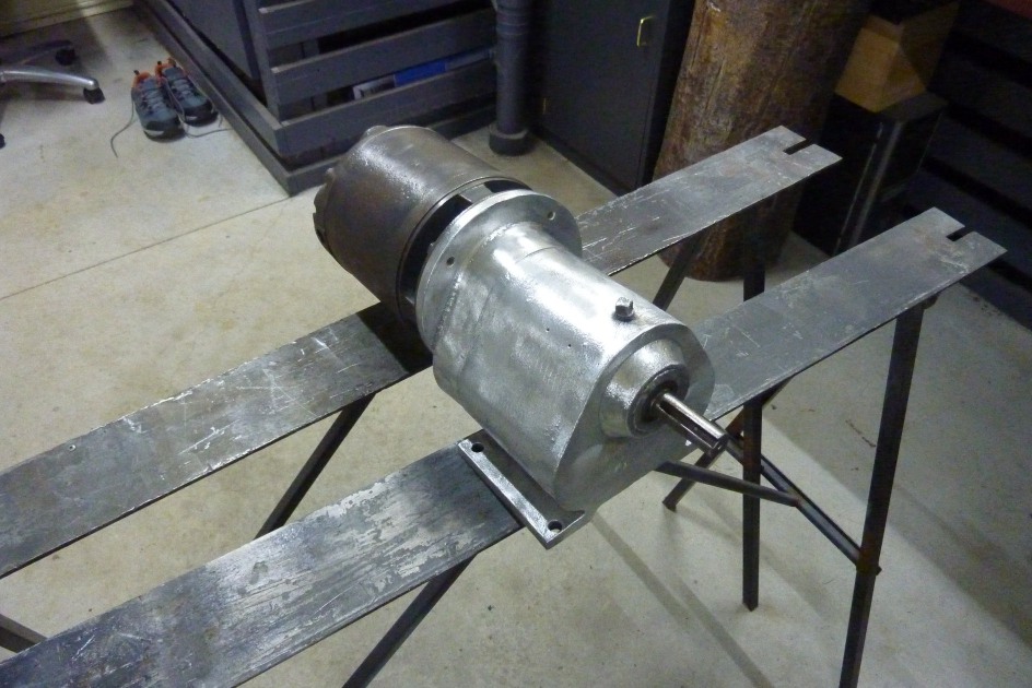

Wire wheeled it and turns out the box has an aluminium case. Hit it with some industrial silver paint.

Welded some brackets to the very bottom of the stand to keep it the most stable that I could. It improved it from before the motor and gearbox was added. The holes were slotted so I could adjust the chain tension and not worry about a spring loaded tensioner or adjustment wheel. Fortunately this motor can be reversed to give me that option. However it is a non capacitor type motor with a centrifugal switch which cannot be made speed variable. So gearing will be critical to make it the most usable.
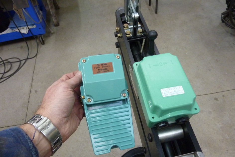
To free both hands and make it safer, I chose to use a footswitch to turn the power off and on. Tend Foot Switch, TFS-402, 15A, 250V. Also a drum switch, QS-60 D5Q2, AC 380V, to switch the forward, stop and reverse. Now from the power point the lead runs into the foot switch first. I removed a section of the outer sheath but only cut and stripped the active wire, brown in this case. The earth and neutral were left uncut.
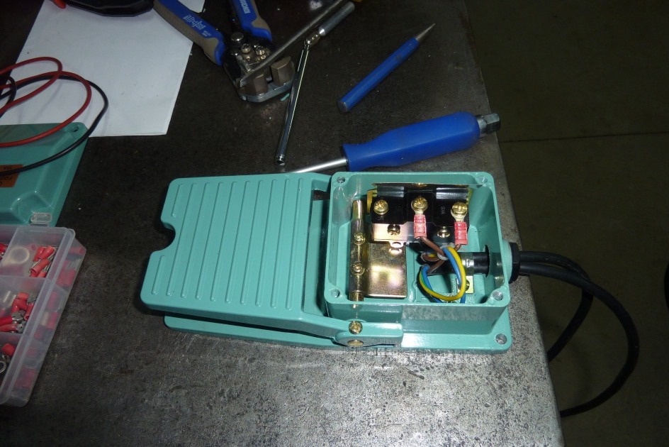
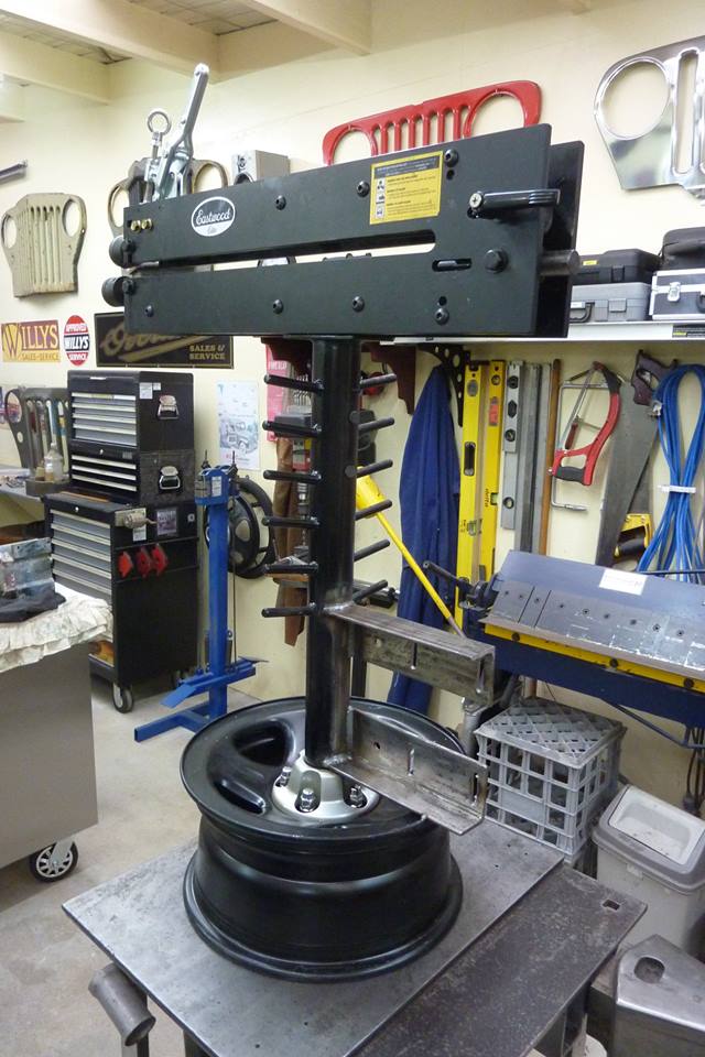
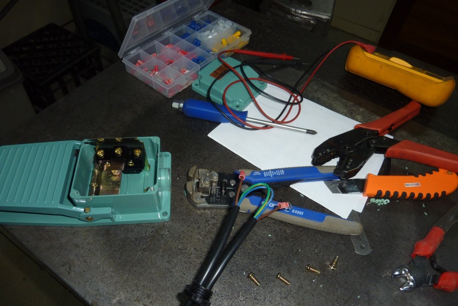
Two ring terminals on the active with one going to the common terminal which is the first one closest to where the cable enters. The middle terminal, power only goes through when pedal is depressed, was used for the wire leading out of the pedal to the A and AZ terminals of the motor in this case. The unused terminal is power off when pedal depressed. The forward-stop and reverse switch was mounted to the top of the bead roller by drilling and tapping the top of the side plates.
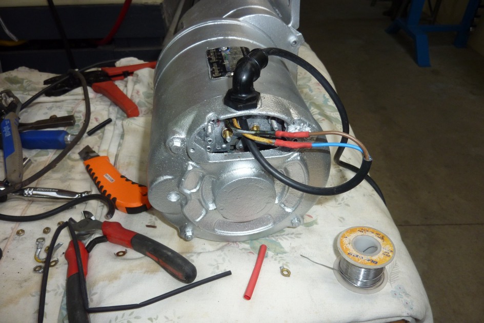

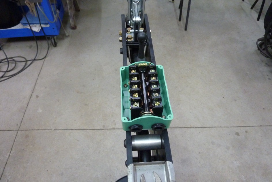
Now the two winding wires that the plate said to reverse the rotation were on terminals A and AZ. These need to run up to the barrel switch and back down again back to these terminals. These are the same terminals that the power wires from the foot switch connect too, for active and neutral, but reversing those won't change the direction of an AC motor. See more information here on reversing induction motors. https://woodgears.ca/motors/reversing.html The winding wires, not the power wires from the pedal and power point, now run directly to one side of this switch. Note the position of the switch lever with the ball on the end pointing to the right. You must leave a set of terminals in between clear and not use the last set for the winding wires closest to the switch lever. With the lever to the right, brown is connected to the other brown and the blue to the other blue.
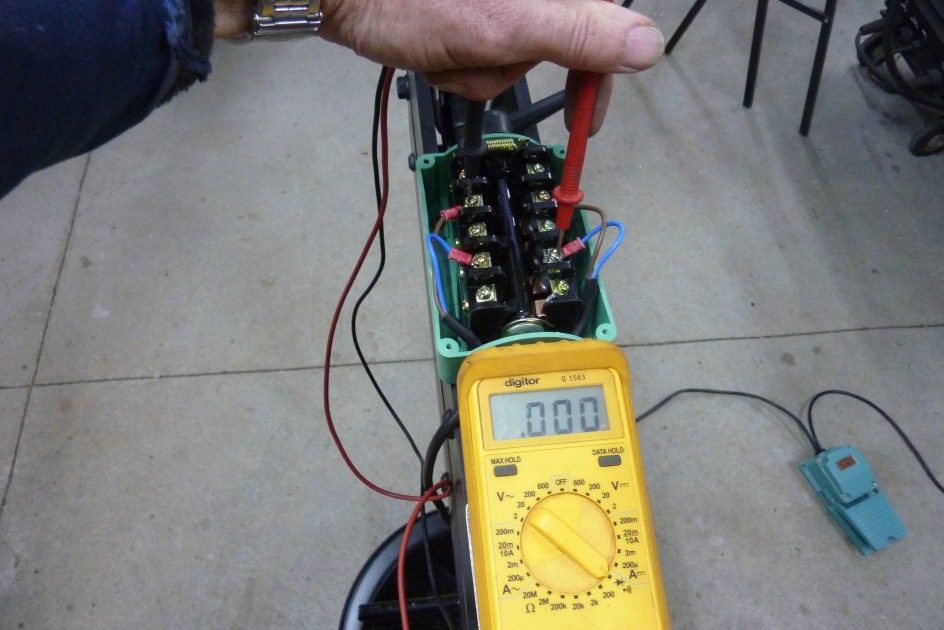

There is no connection between the brown on one side to the blue on the other side of the switch. Now with the switch lever to the left, there is no power going from the brown on the left side to the brown on the right side of the switch.


Instead the brown on the left side is connected to the blue on the right side and vice versa. This is how the winding wires are switched over before they go back down to the motor to attach to the A and AZ terminals. I made sure the lever points in the direction that the metal will travel through the bead roller. You can switch the blue and brown wires on one side of the switch to alter it if it goes the other way. Or use the first and third set of terminals instead looking from the bottom as pictured.
[INDEX]