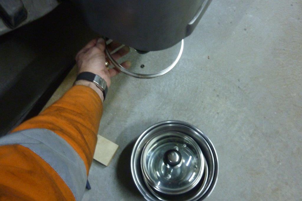

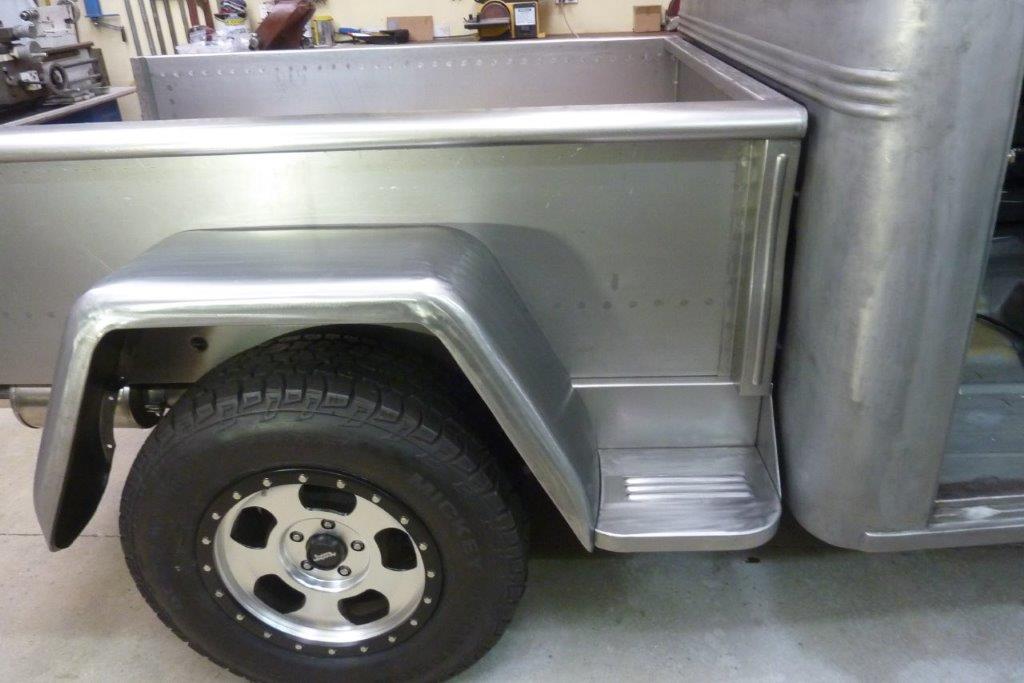
I have the depth matching the bottom of the cab. The stock ones had a curve like the back of the cab. Raided the kitchen to find a matching radius. :D
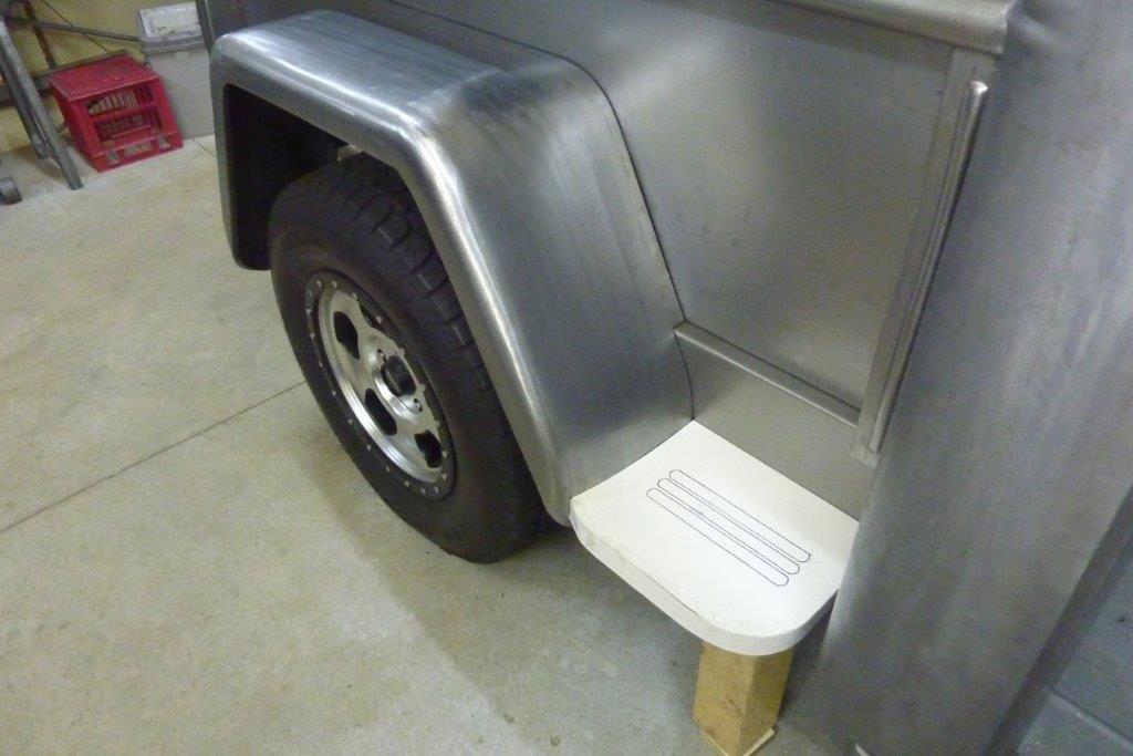
With the curves to the leading and trailing edges like stock, it looks much better. Will also add the bead rolls that the stock ones had. I don't like seeing the 'hole' in the corner under the cab where the sill curves up to meet the floor. This is normally not seen but is now because of my wider cab.
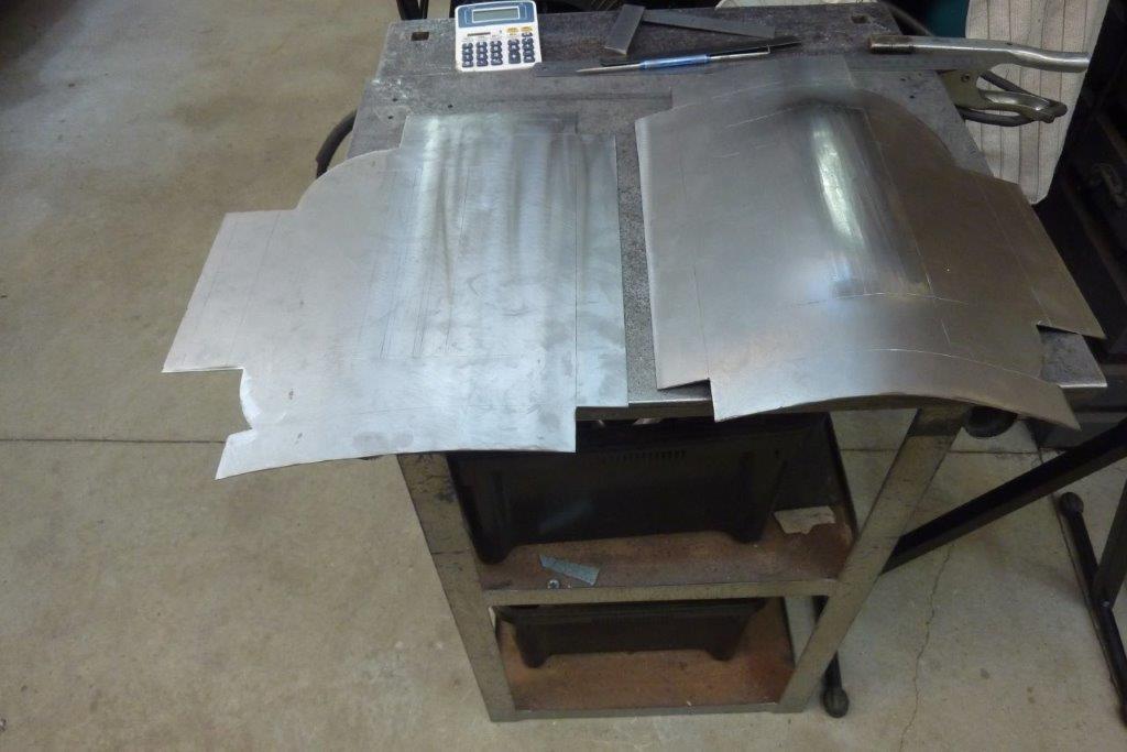
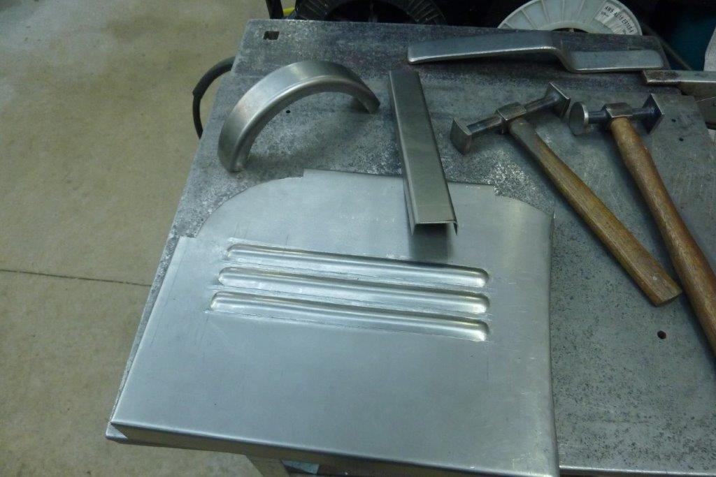
Thinking I will also add a brace at the front to act as a support, but also cover that hole in the corner. Frames the step better too. Making the steps. Doing both sides at once as quicker and it also makes sure I don't make two of the same side. Think we all have done that before! Also showing how much I have pre-stretched the right one where the beads will be formed.
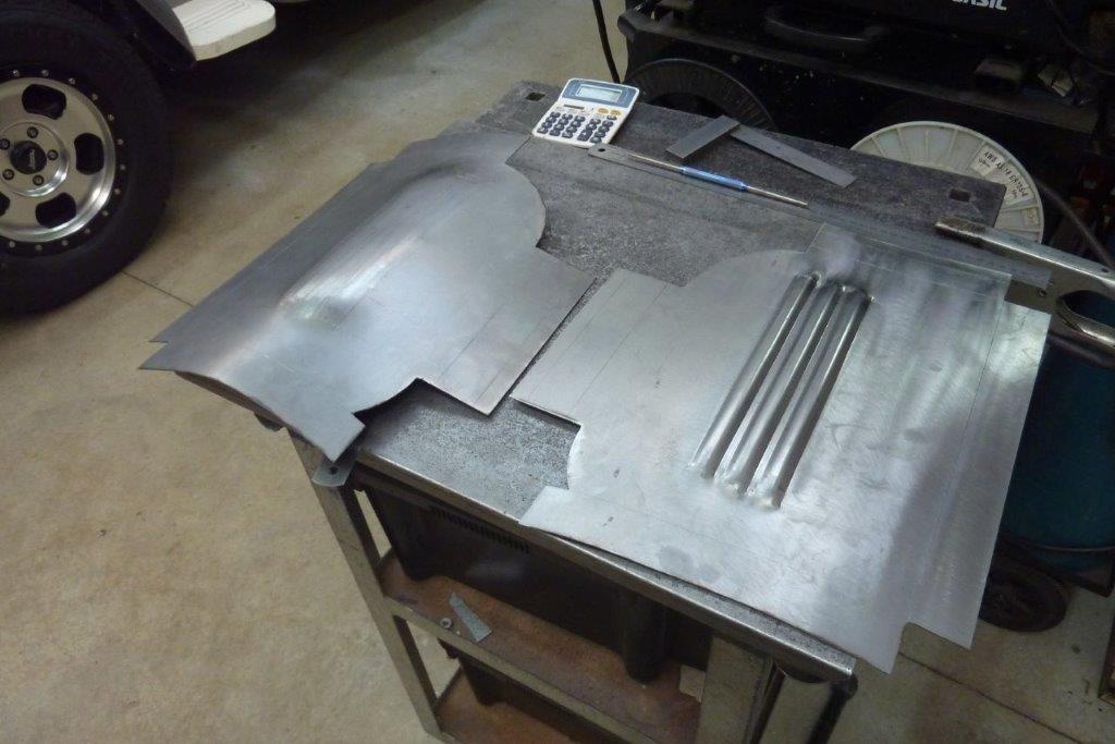

Looks like I guessed well as very flat straight off the bead roller before any other work has commenced. Left one ready to go next. I had these bead dies made for me the last time I was in the USA by Hoosier Profiles. I designed them to be offset so that the thin side would match the stock bead spacing. Last bead is only on the first pass.
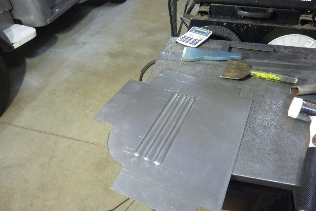
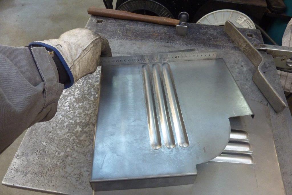
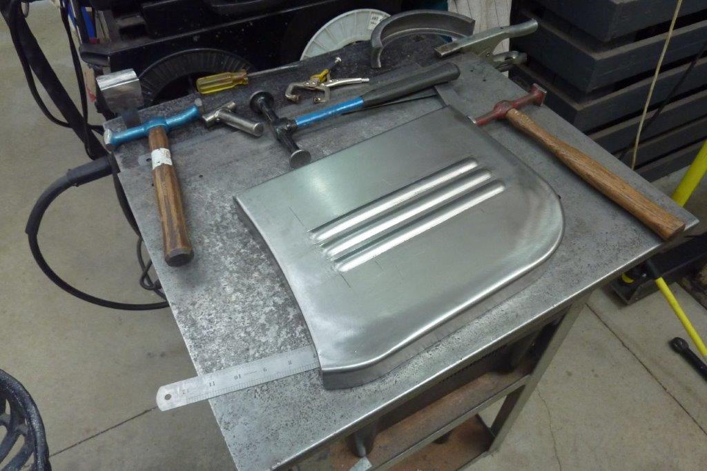
I dressed the ends by rounding them using some notched water pipe. Also used the bolster and chaser down the sides of the beads. Came out dead flat in every direction.
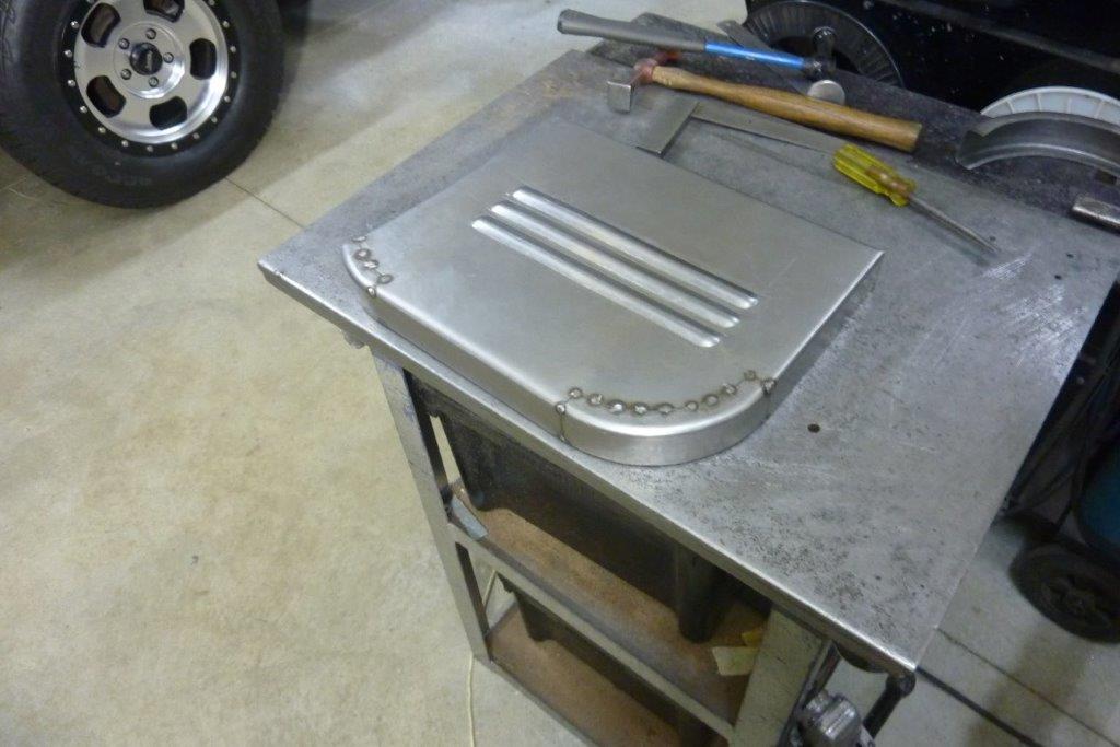
I had decided on doing the curved sections separately by folding some channel and then shrinking the flanges to match the curve. Tacked in place ready for tig welding.
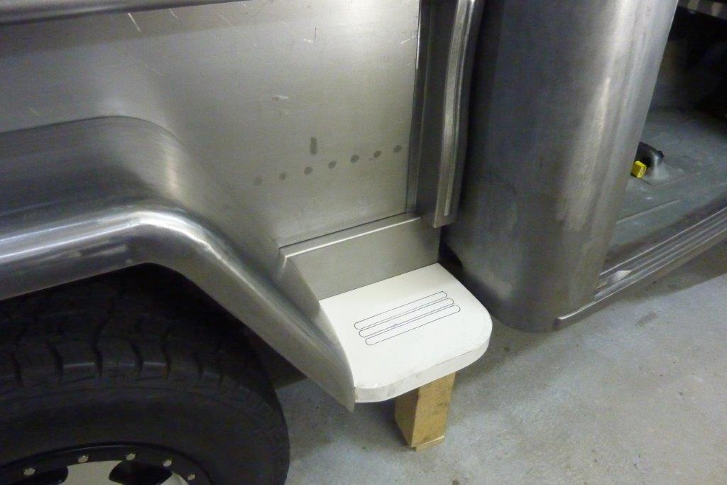
I used a softer radius for the front top edge and made the other bends the same as normal for that thickness of sheet. The shallow curved side is to match the crown of the guard. Got it clamped into position to check fitment.
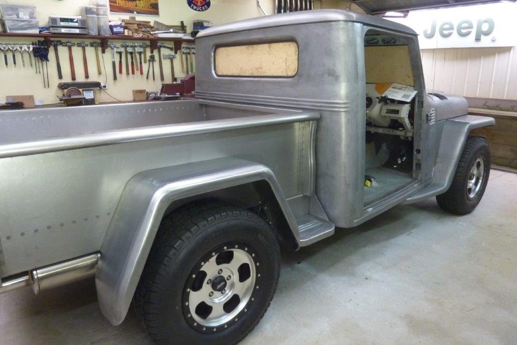
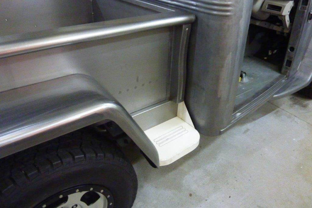
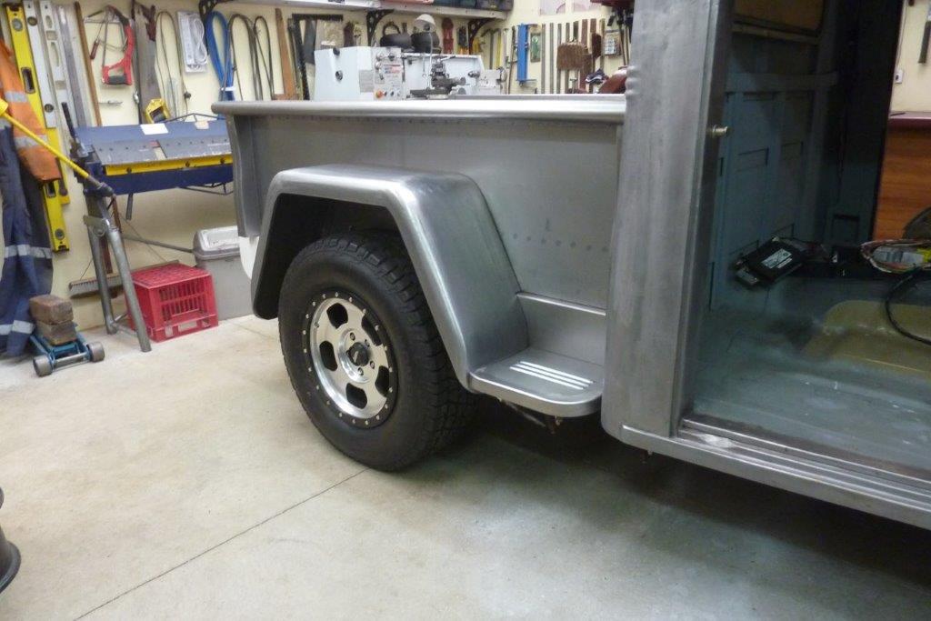
All bolted in. I also added support straps from the bottom of the skirts back to the chassis which greatly removed the flex the guard had. Stock they ran a rod from the bottom of the guard back to the chassis as well, but most times they are missing which leads to all the fatigue cracks. The step also stops racking and will minimise the stone chipping on the front face of the guard.
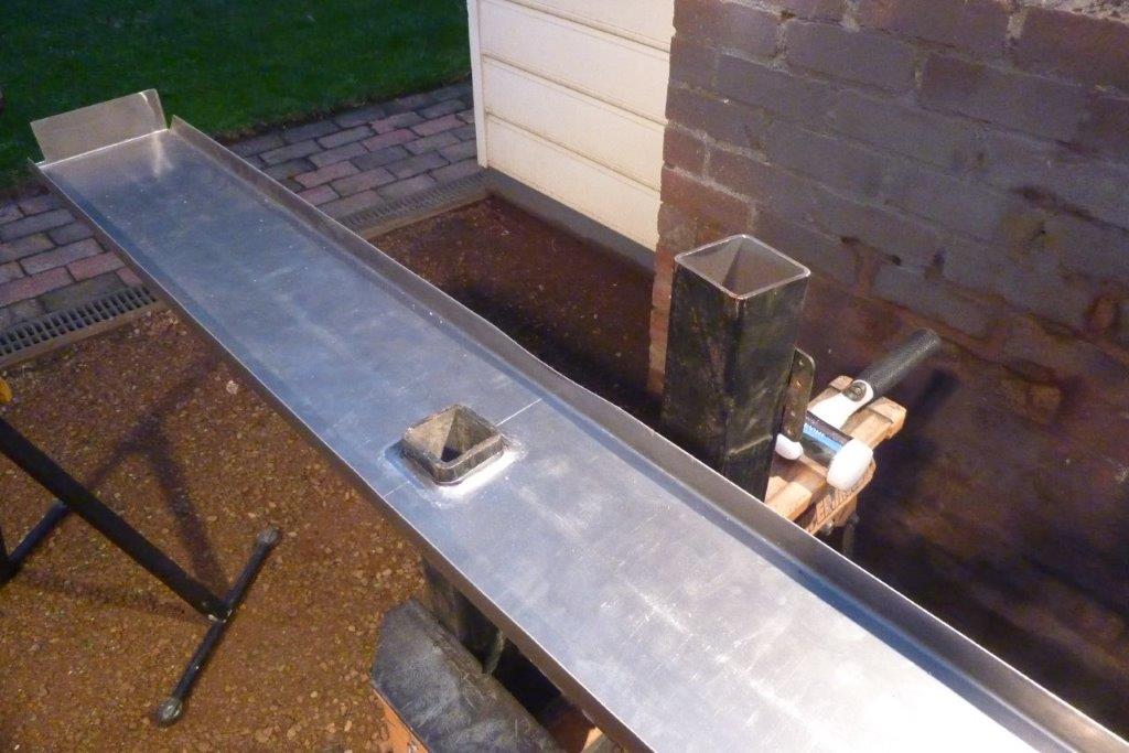
I am flaring the hitch hole in the rear valance panel. Hole was cut smaller and placed over some 50mm/2" tubing, the same size as found on the hitch tongue. Hammered a piece of 75mm/3" tubing over it to force the smaller tubing through. Ground a bevel on some 65mm/2.5" tubing to use as a dolly to finish shaping the flare.
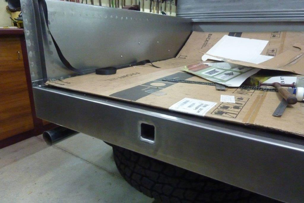
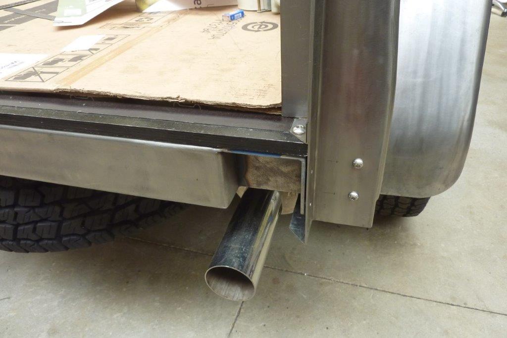
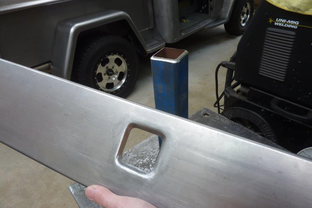
Gives a neater appearance than just a flat square hole. When making this rear floor support I also included a section that went through the bed side and ended up inside the stake pocket. I have now drilled through the stake and into the support and drilled and tapped it for the two button head bolts. This stabilises the end of the bed. Notice the gap between the bed side and the other part of the same support bracket. This is where the flange at the end of the valance slots in between and two more bolts are drilled and tapped to hold the valance in place as well as further support for the end of the bed.
[Index]