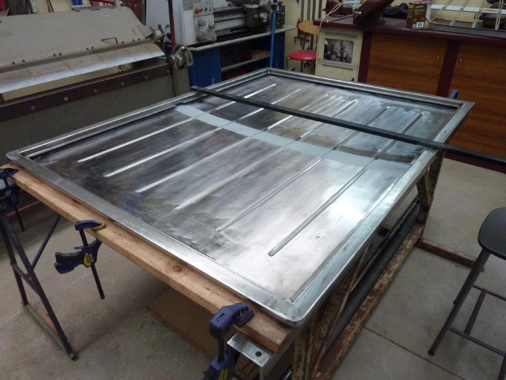
Prepping the area ready for the crossmember to go in. I left the brace in place to make sure the flanges didn't twist during welding or pull together. Here is a trick I picked up from Rod Covell from his old Street Rodder column where someone had said they had a problem with the adhesive between the roof panel and crossmember showing up in the reflections of their polished paintwork depending on the temperature of the day. Manufacturer's use this method on boots and bonnets etc, but the blobs of adhesive are quite thick and the frame is a good 5mm-5/16" away from the skin to help with the movement. So he said that he uses the loop/soft side of Velcro as a cushion to protect the paint from rubbing and to stop it rattling. I have used it with success on my roof cross member as well.
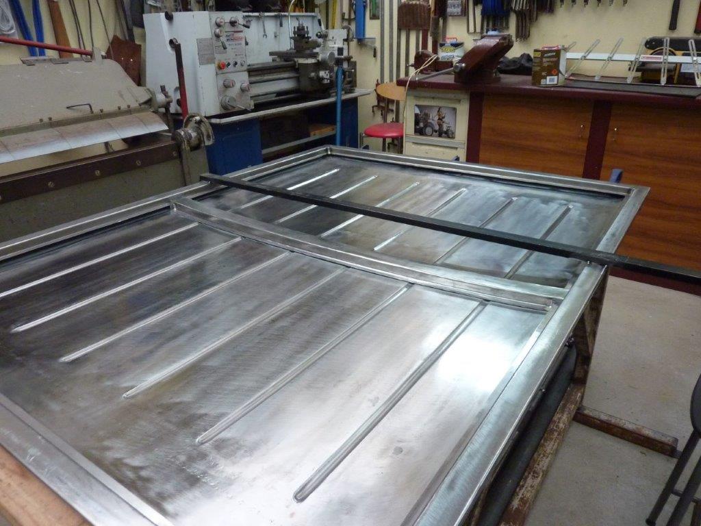
Cross member dropped into place ready for welding. Follows the crown nicely. :)
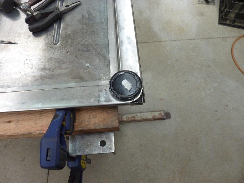
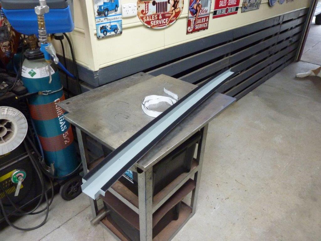
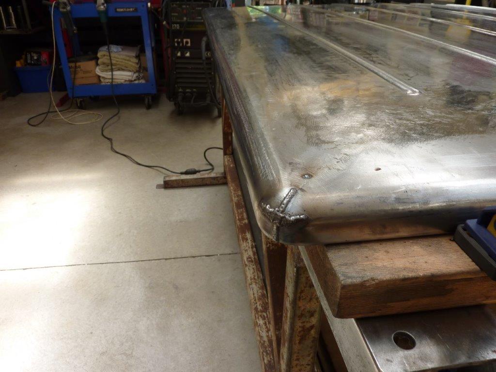
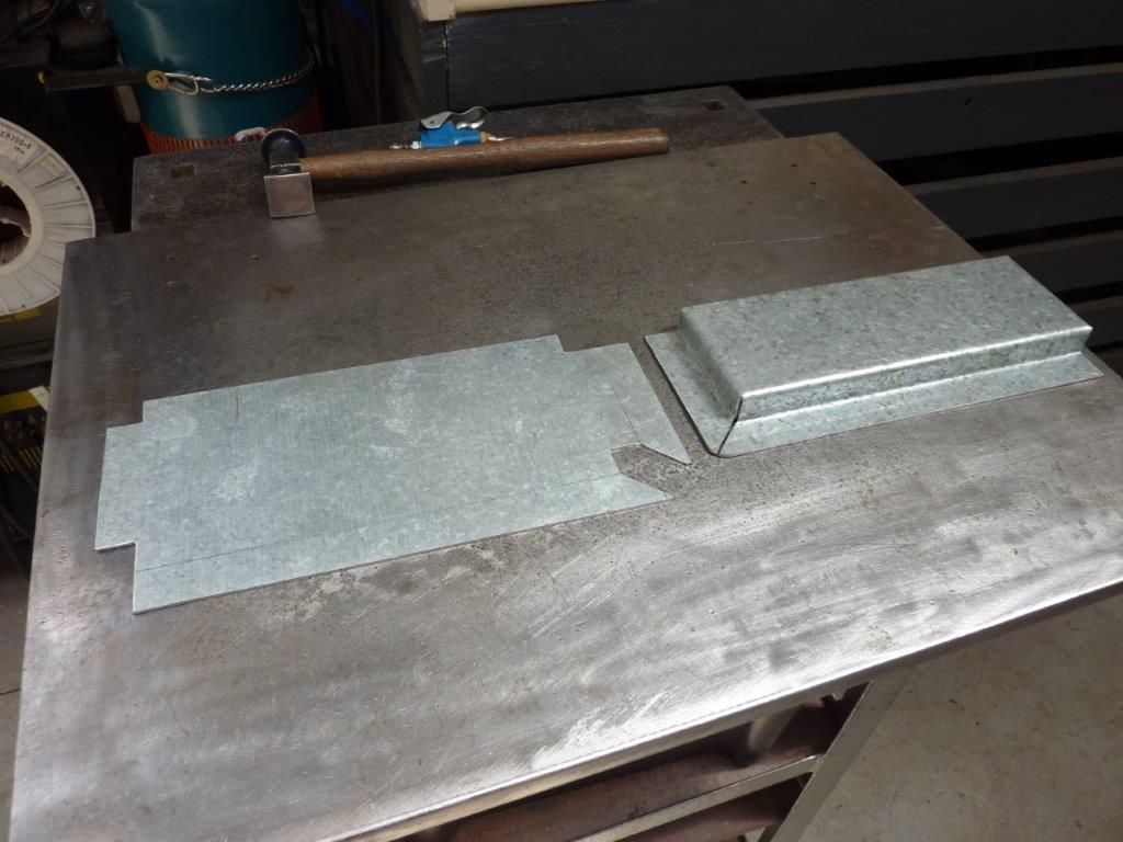
I never wanted the sharp corners on the cover which is why they were never welded. The plan was always to radius the tailgate end of the cover to be proportional to the radius at the end of the bedsides. The jam lid was just the right size and you can see how I have cut away the underside of the cover to match it and slot the vertical part of the sides. I pulled the vertical parts around to follow the base.
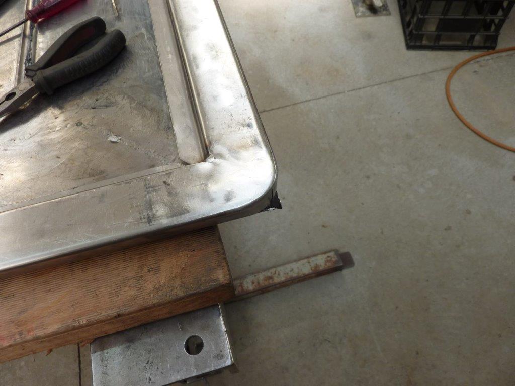
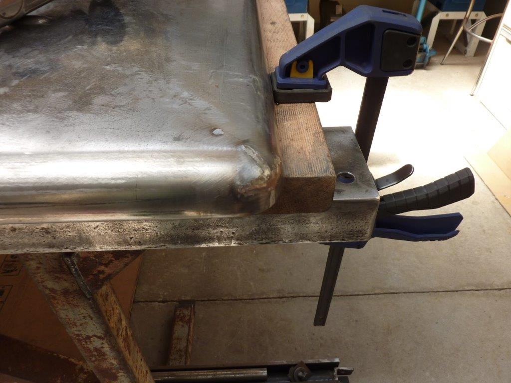
From the top I could then make adjustments to the radius of the vertical part before bring the top down to meet it. I slowly cutting a triangle out of each side of the very top part and tapped it down to give it a radius rather than a ridge.
Once it rolled over the curve I could weld it shut. Ground it down to almost flush.
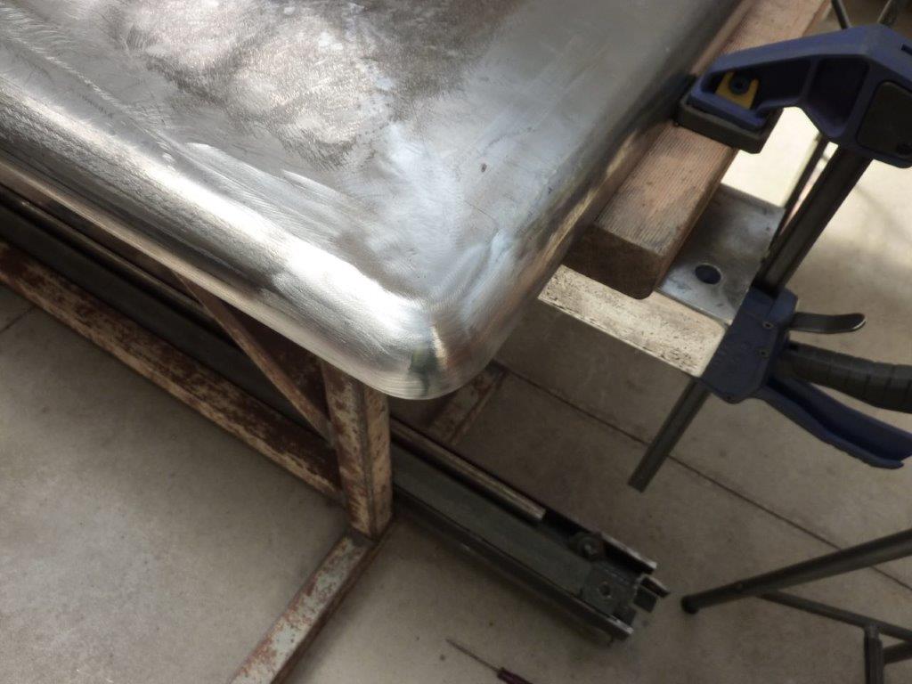
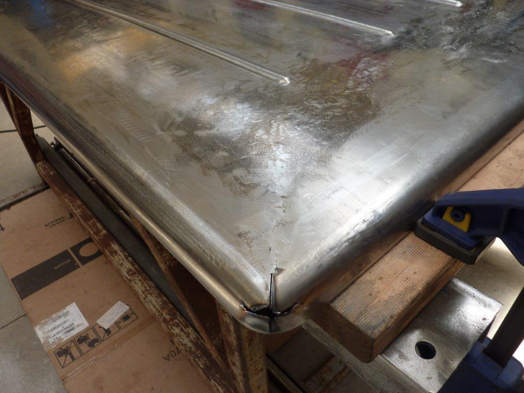
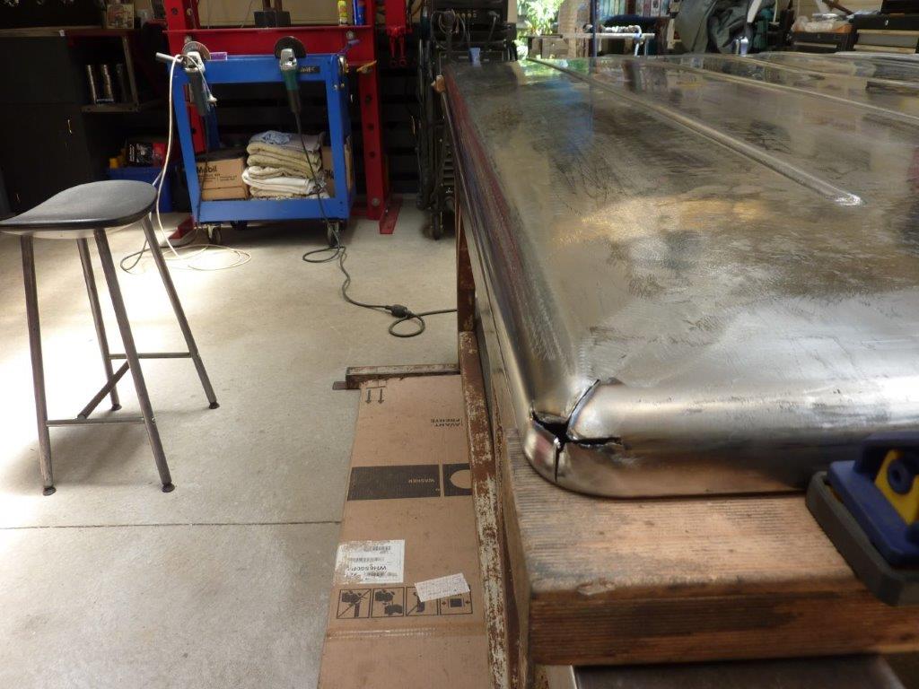
Then finished off with a flap disc. At the cab end of the cover I just matched the radius to that of the ribs, as the bedsides are squared off at that end.
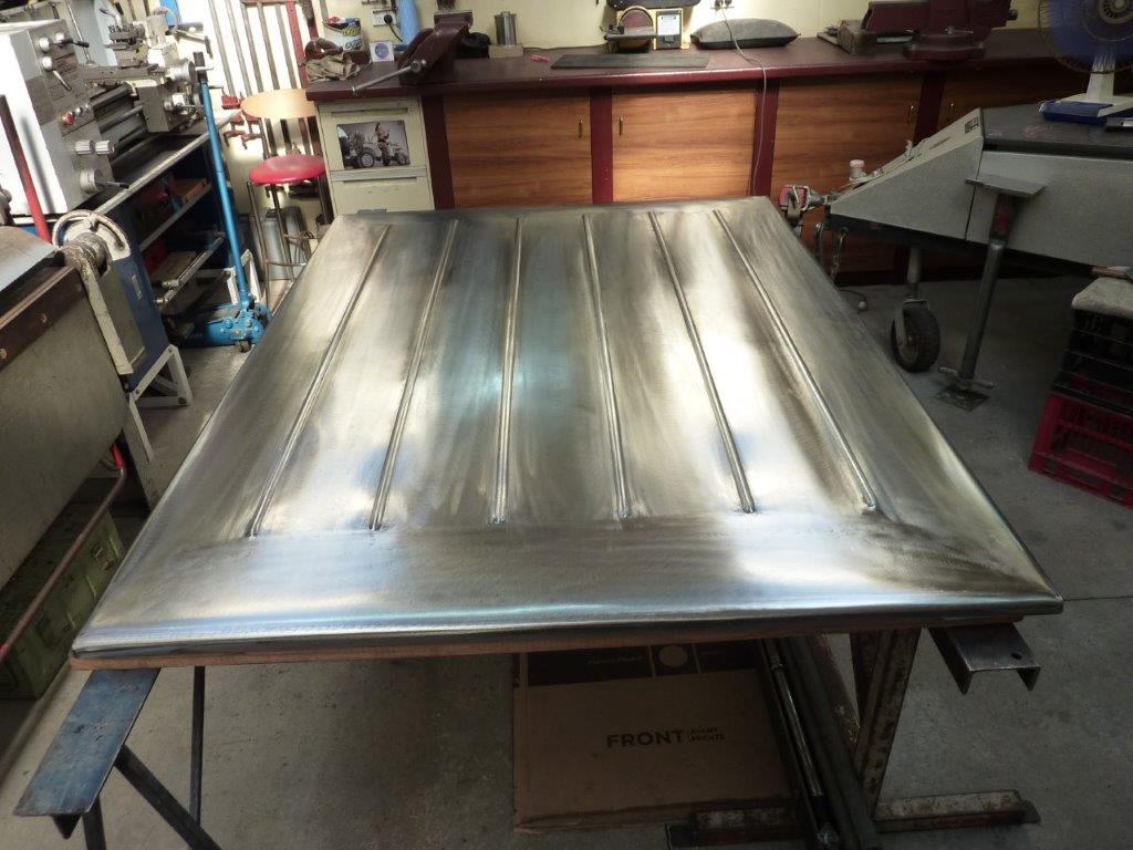
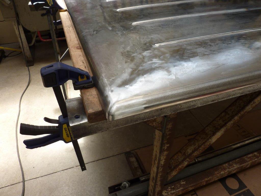
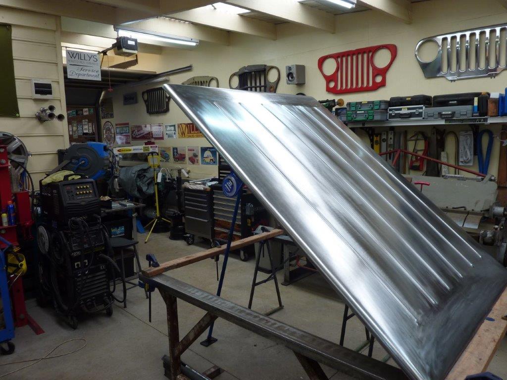
Every time I had been waiting for heat shrinks to cool, I was lifting the little low spots and planishing down the high ones. The final sand was just to remove the heat discolouration and most of the shrinking disc marks. I then followed with a 7" strip disc. I'm pleased with the way it has turned out and is exactly how I imagined it. :)
Video update
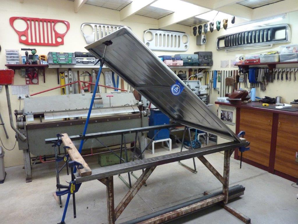
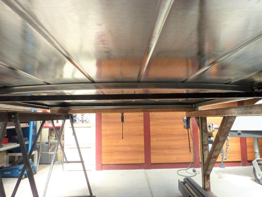
Working out how high we want it to raise. We settled on 40*. 40* should give us plenty of room around the hinge area to still get things in and out.

Making support mounts for the hinges to bolt to. The weird arrow shape is what you need if you have a step down and a flange and want it to fully meet in the corner. I had been looking for some time to find a hinge like this that was a stronger version of a sofa bed hinge where it lifts up and back at the same time.
[Index]