
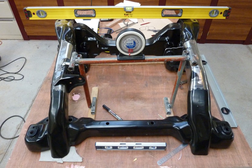
I set the floor and firewall up in place to make sure previous measurements were correct. They were exactly right but it was still nice to confirm before I go welding in the engine mounts. Also checked the radiator position to see how it would all fit within the engine bay. Then setup my engine mount jig 175mm further back so the engine sits the same distance off the firewall, but centres the front axle in the wheel wells. Had to raise it 3/4" above the what it was in the engine cradle originally to clear the diff mount, but is still an 1" lower compared to the original floor height. Having it this far back will give much better front to rear weight balance for better handling as well.
Made some new mounts up. Bit overkill being 102x150x6 mm RHS, (4"x6"x1/4"), but had the perfect internal size to match the engine mounts on the block.
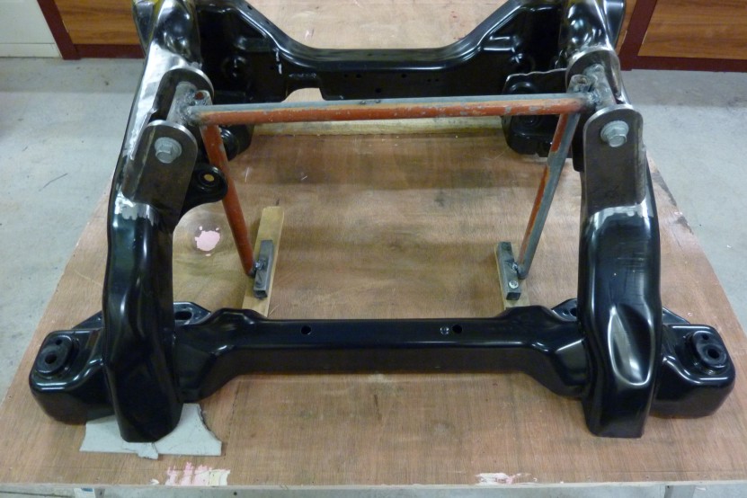

Tacked them into position then put the cradle back under the engine to test the fit and make sure the angles and position was perfect. Fitted like a glove and just pushed the bolts through with my finger. Everything cleared just as I wanted as well so the jig was worth making.
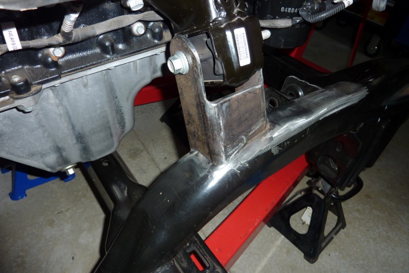
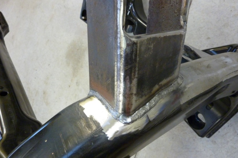
Right side shown and also it fully welded in.
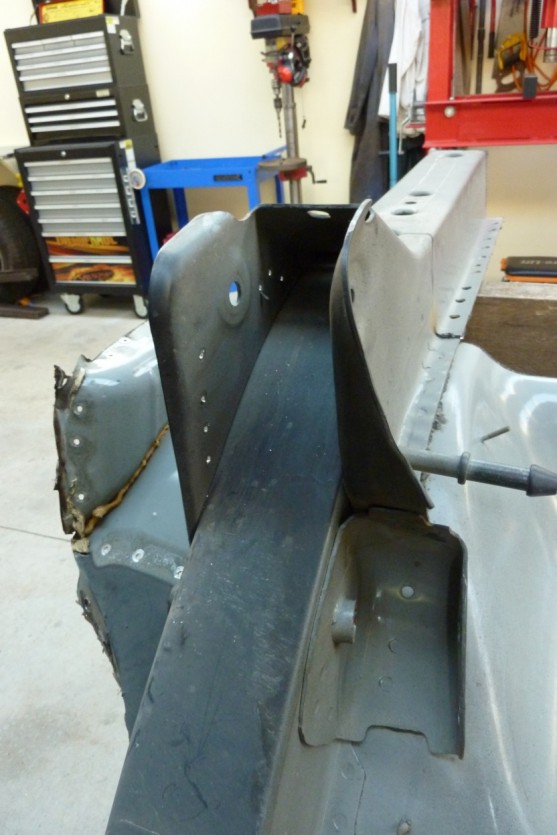
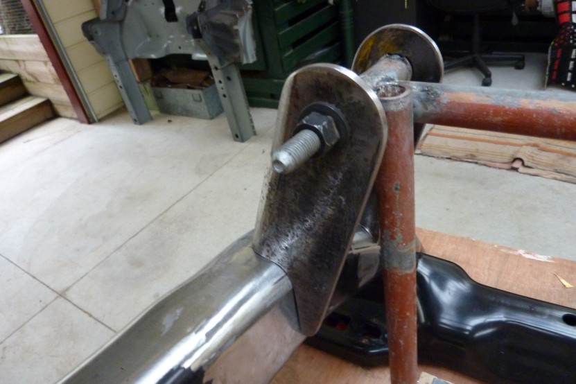
So here you are looking at the rear suspension setup
on the Grand Cherokee upside down. I am hoping to reuse these brackets on the
Willys. All the suspension mounts are made with HSLC, (High Strength Low
Carbon), steel.
http://en.wikipedia.org/wiki/High-streng
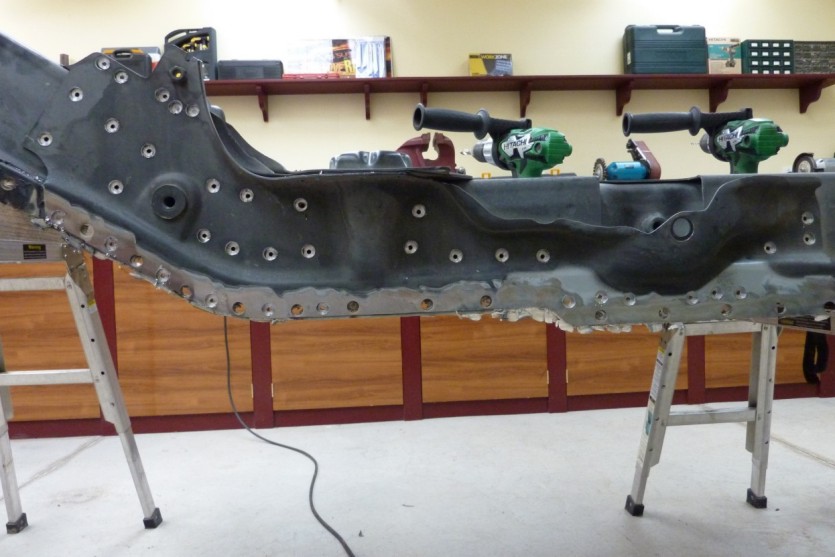
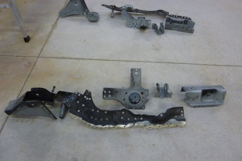
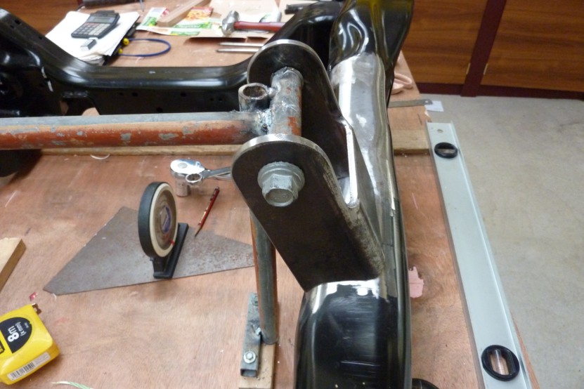
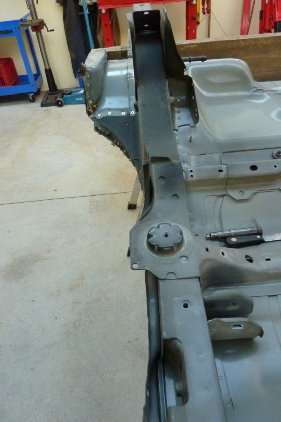
More spot welds to drill out! This reinforcement plate on the outside of the frame supports, from left to right, the swaybar, coil and shock mounts. Remembering that it is still upside down. The next picture also shows another bracket which is duplicated on the other side as well and is what the panhard rod frame bolts into.


As I cannot attach to the inner guard of the Willys due to having a separate frame, the two mounts will be braced across the engine bay to each other instead. So I cut off what was not needed but left an extra inch out from the coil over bolt area. To improve its appearance, the pressed up part that goes over the shock pin was blended into the flared edge which I continued all the way around to increase stiffness. The flare was rather difficult as the HSLC steel has a 50% greater yield strength and requires 40% more force to form it. Even harder on the sections that were double thickness.
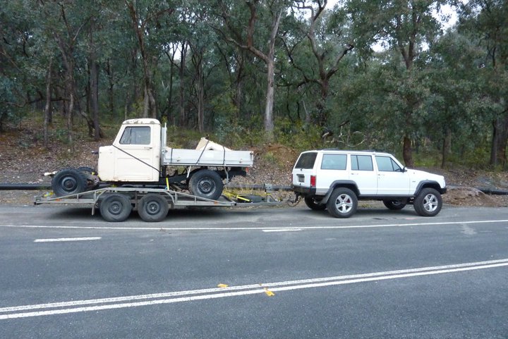

Well I finally got another Willys that I was after. Had to go interstate to get it and slept overnight where pictured above on the way back. This one was registered in NSW as a 1948 Willys Pickup and has the small rear window that I really wanted for a more hotrod look.

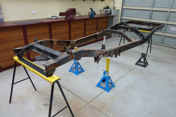
Can see the difference between the two rear windows with them side by side here. So I stripped this frame down to the bare rails and will use these as the bases of my build as it is in better condition than the other frame. It also means it will be registered as a 1948 Willys too, as here in Australia it takes the identity of the frame and not the body. My body will be made up of a mixture of both as will use the middle of the 48 with the 58 grated onto each side making it 7" wider over all in the process.
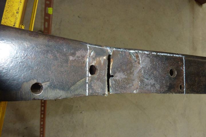
Once I had this frame down to bare rails, I started making repairs, cutting out and replacing a few areas of rust where dirt had been trapped above the rear bump stops and at one of the cross member junctions. A piece from the other frame rail was cut out and shaped to fit the area. The joins were bevelled and penetration checked after welding to make sure it went all the way through.
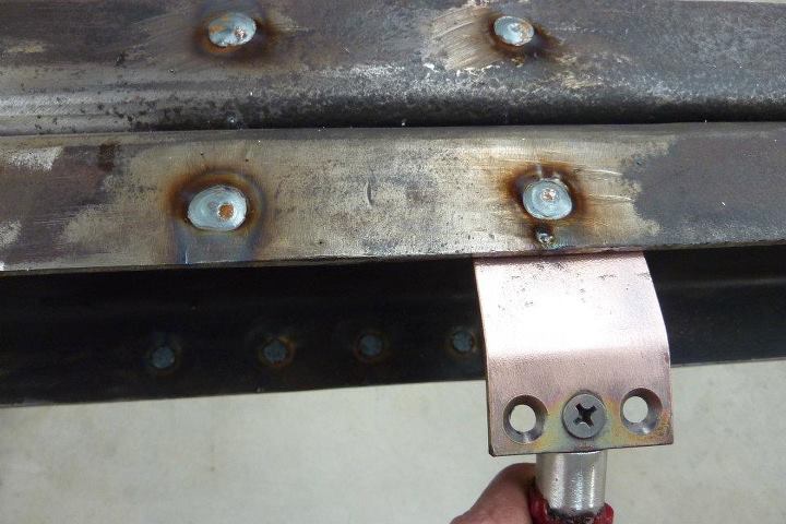

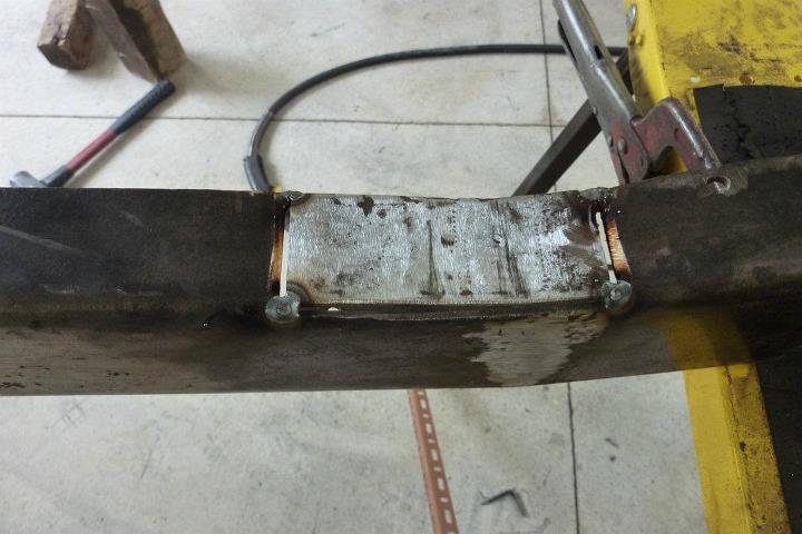
Also all the holes left from frame brackets and rivets etc were welded up. The easiest way to do this is holding a piece of copper underneath the hole as the weld wont stick to it. Can use brass or aluminium too. What I am showing here comes from Eastwoods. The rear cross member had all the holes welded up as well. The bigger PTO hole had a washer of the same metal thickness welded in first.
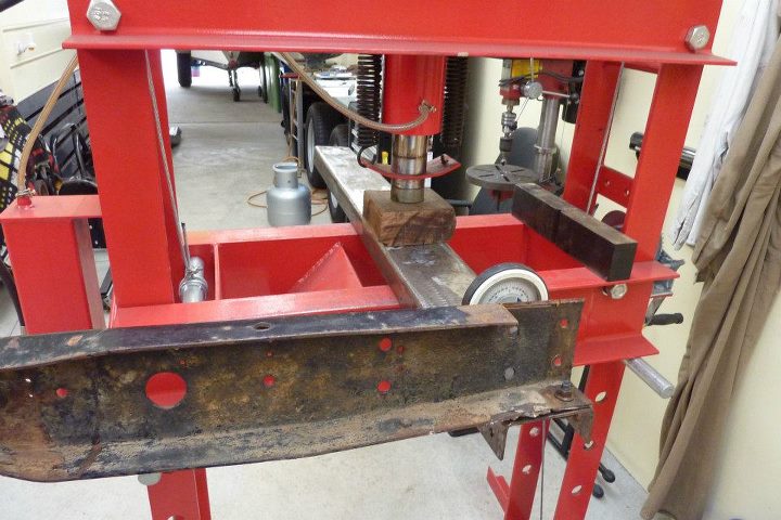
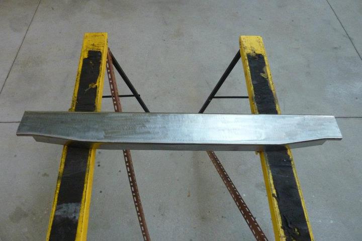
The cross member also had been bent up in the middle 3*, due to most likely landing on the towbar tongue that was attached to the middle of it. So the centre was held in the press while the ends were levered down to make it perfectly straight again. Looks a lot better now, ready to have a Hayman Reese type receiver added and be boxed .
[Index]