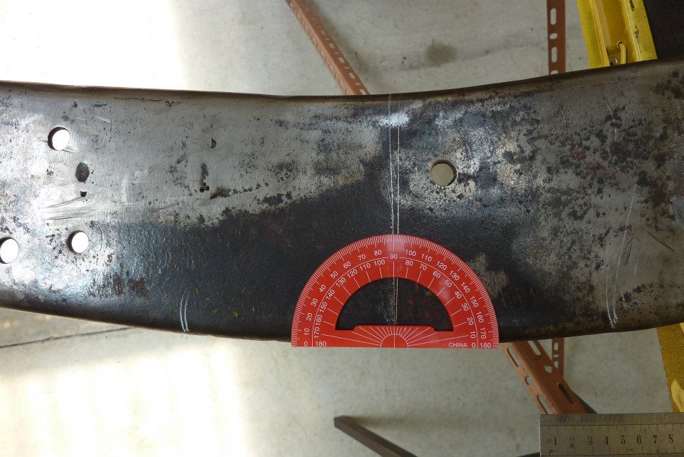
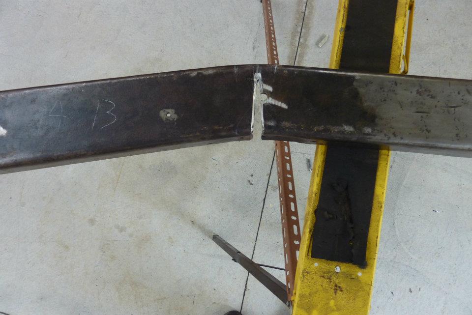
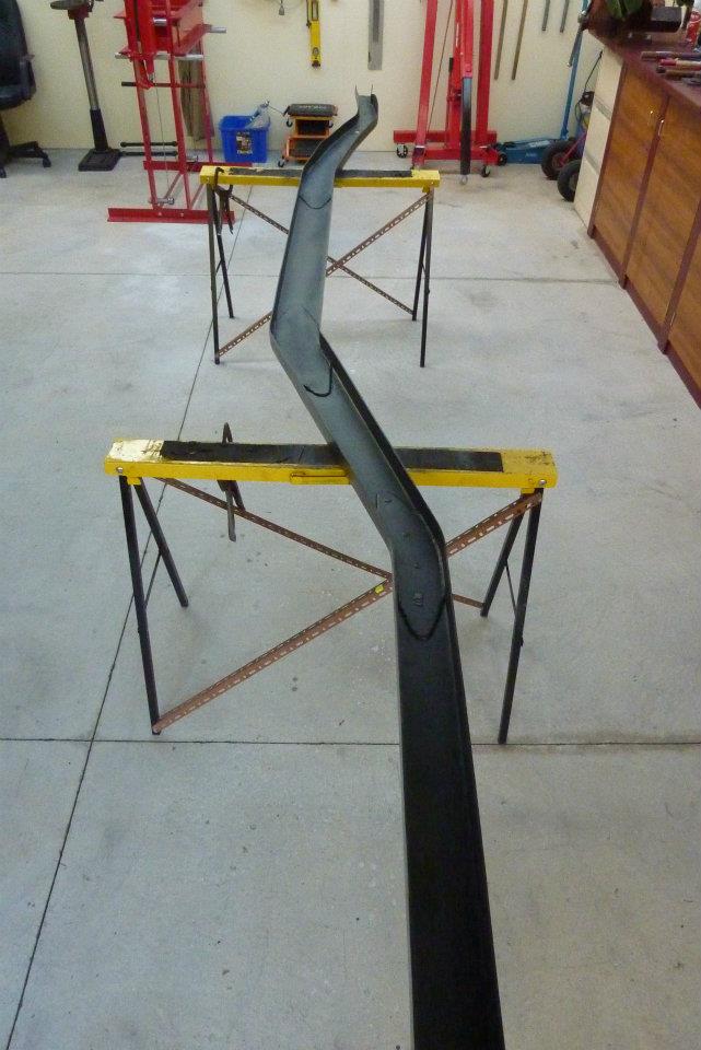
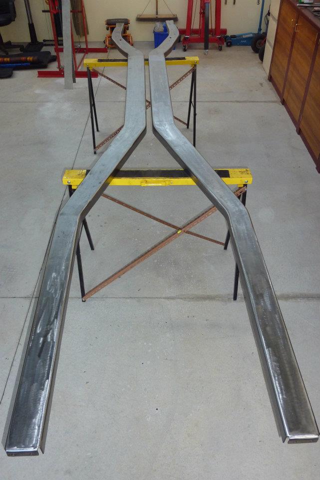
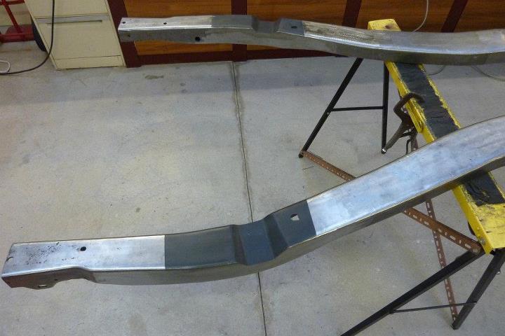
Needed to raise the front of the frame so that the engine cradle from the Grand could bolt in and still keep stock height. Only had to come up 1.25" so made a cut in the frame at the existing bend where it rises up from under the floor at the firewall. I didn't cut all the way through so I wouldn't get a sharp bend.

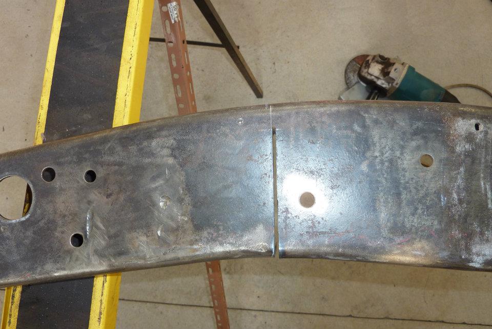
Placed it in my press where it needed little pressure to close up the gap which had been already bevelled to a allow full penetration weld.

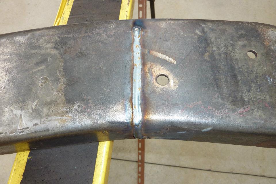
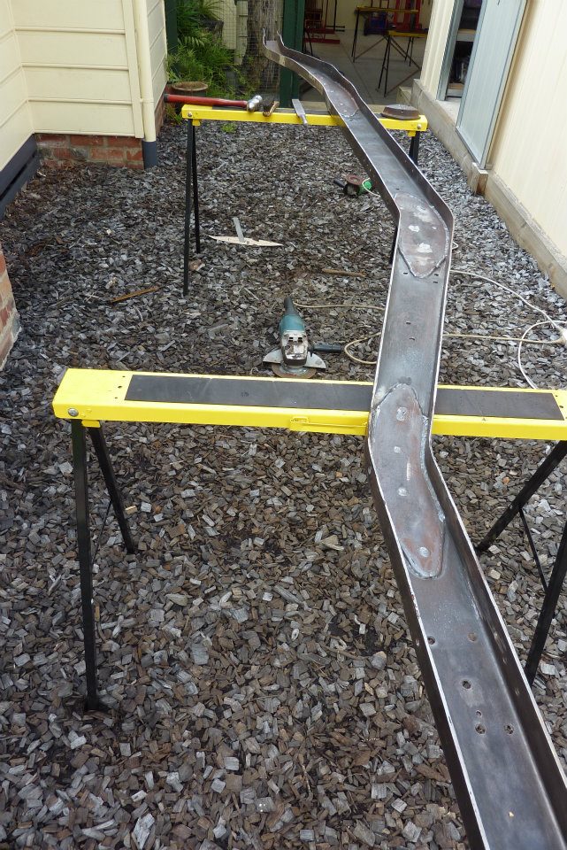
Ground smooth and you can see it retained the stock curve. Also did the same at the back of the frame as needed an extra 4" rise over the rear axle. The original bend after the cab and over the axle were tightened 7.5 degrees to get the rise I needed.
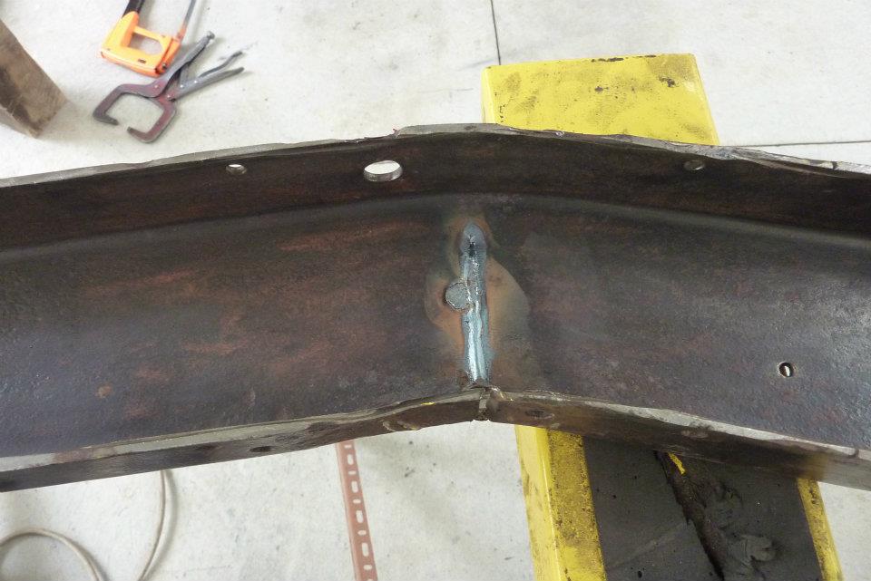
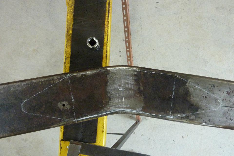
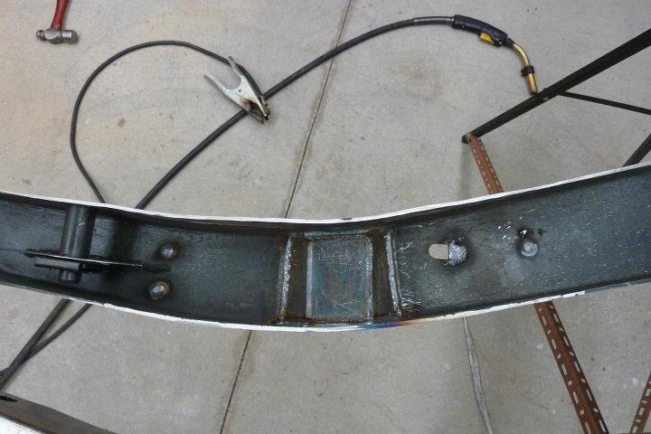
Showing the full penetration on the back of the frame. The round spot off to one side of the weld was where an old rivet hole was welded shut. Next photo shows the laying out the fish plate on the opposite side to which it will be installed. This is the way I do them using the Government Street Rod Manual as I guide and what I was taught working in the structural steel industry. Only thing changed is the radius on the ends to remove a possible stress riser there. It needs to be of the same material thickness as the parent metal of the rail, 4x longer than the height of the rail overall. Half of it will be without taper with the remaining 25% each side tapering off to a radius 25% of the height of the rail. So in this case the rail is 4" high so 16" long with the taper on each side 4" long to a 1" radius. I just use a socket to draw around. The reason for the taper is so that there is a gradual increase/decrease in stiffness in and out of the bend. This stops stress risers from occurring. Same reason for rounding the ends as well, a point would cause a high stress concentration.

Used the old frame rail from the 58 Willys to cut all the fish plates. The old holes will be useful as plug welds in to the frame. All rust was removed from where the plates were to be welded in and coated in weld through primer to stave off future rust.
Then the rest of the inside of the frame had all the surface rust removed along with any old paint before it got treated with the high zinc weld though primer as well.
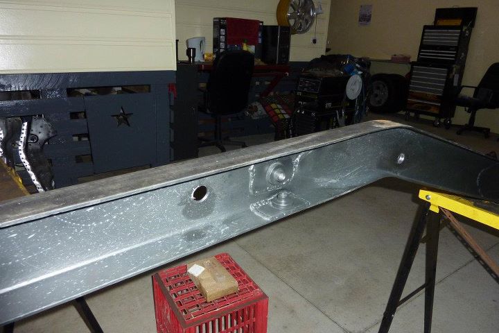
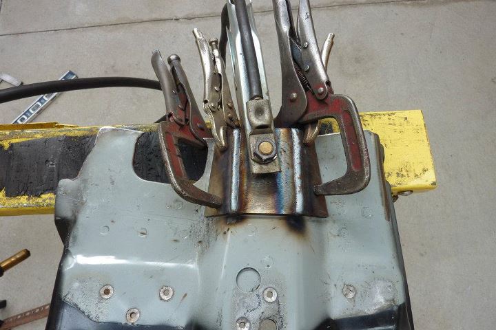
Original threaded bosses were cut from the donor Grand Cherokee and welded into the inside of the rail where needed. Also shown is the swaybar mount which was welded in from the back side and will penetrate the boxing plate once fitted as well.

Above is the cross member and front engine cradle mounts. They have been mounted in the exact same way as was in the Grand Cherokee. You will see later how they come through the boxing plate so they can be supported and welded on both sides like it was originally.
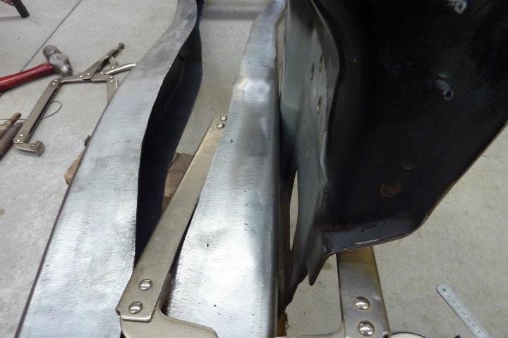
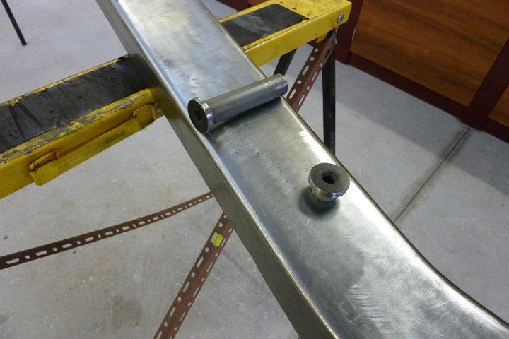
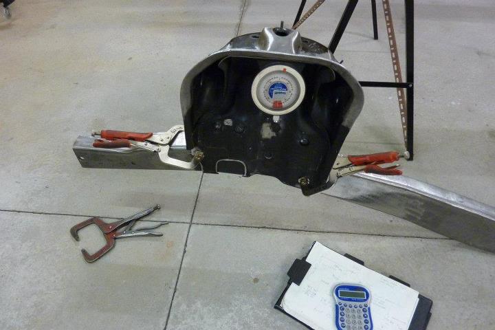
Next to be fitted up was the donor upper wishbone and coil over mounts. As you can see it does not sit flush on the rail. The pressing here is for extra lateral strength and to clear the coil over. It needs to be recessed into the rail to centre the load more above the rail and reduce twisting leverage. So some plating for the recess was made up. I find it easier to weld them over the actual mount so all the angles are correct.
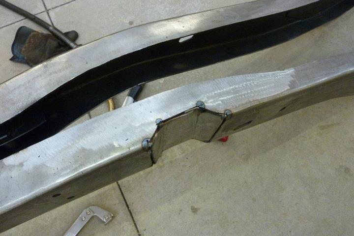

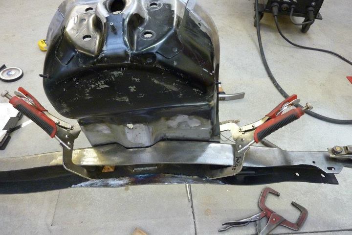
Before the recess was cut out, I extended the wider flange section of the front of the frame further back. You can see the difference with the unmodified rail behind in the first shot. The extra width was the same as the recess so no strength was lost. The mount was clamped back into place and then the boxing plate tacked in from behind to make sure it was position correctly.
The plate was fully welded in from both sides. The area that would end up of the rail that the mount would cover was coated in weld through primer to help prevent corrosion between the layers.
All angles and the position is double checked against what I recorded before pulling apart the Grand Cherokee. I even have it over the same bit of concrete to keep things as accurate as possible having recorded the measurement on both paper and photos.
[Index]