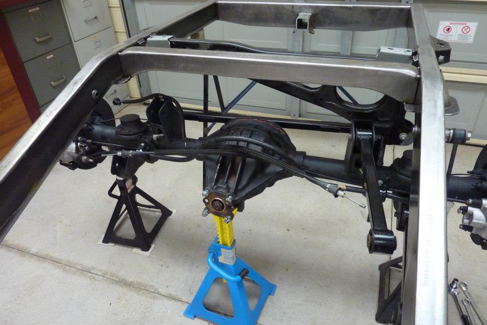
Time for the rear end to go in. The donor runs a Chrysler rear axle with a 8.3" ring gear, electronic limited slip diff, 3.73:1 diff ratio, 12.6" discs with ABS. Axle was centred exactly under the upper coil mounts at the stock Willys wheelbase of 118".
The panhard mounting member was bolted in and it centred the axle perfectly. The inside of the lower control arms lined up with the inside of the frame rails.
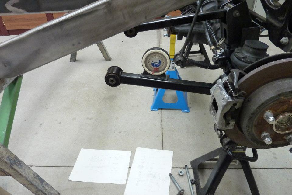
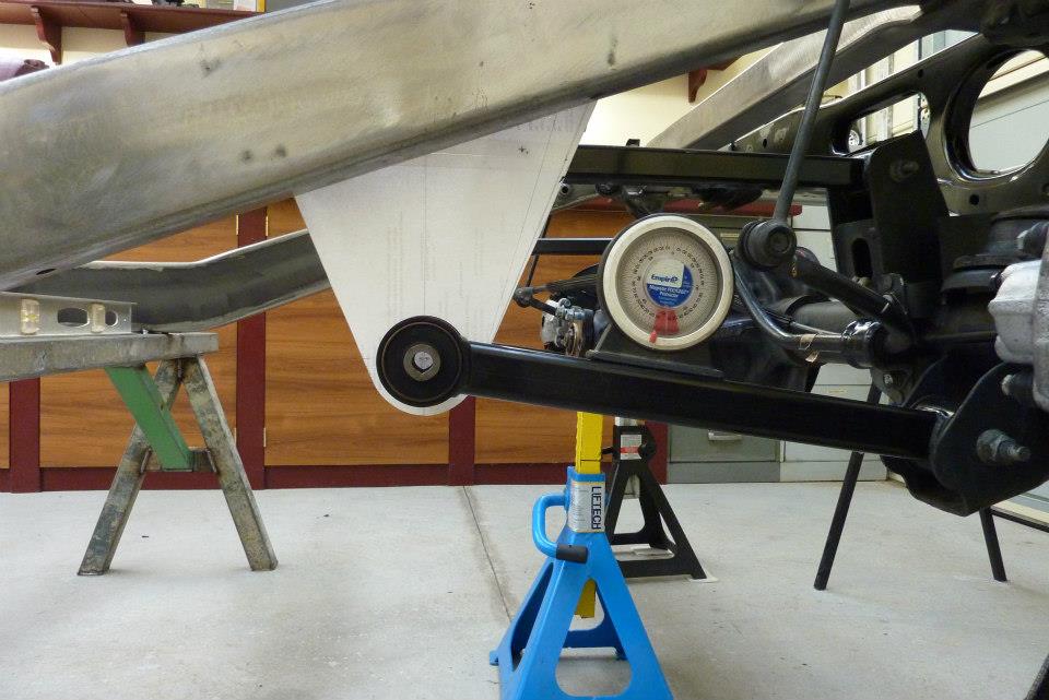
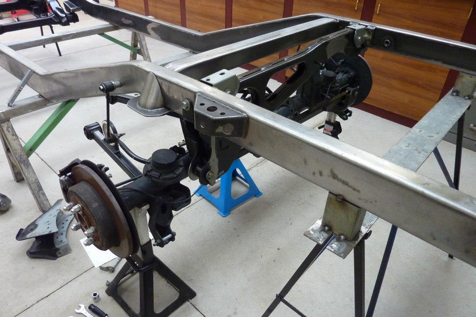
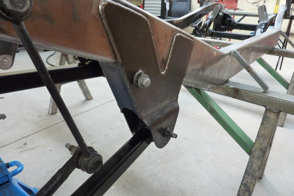
With the axle sitting at the exact height in relationship to the other suspension points already mounted to the frame, I could set the arm angles up the same as factory. This will give me the correct roll centre, anti dive etc as the Jeep engineers worked out in relation to the front end arrangement. Just did a rough layout using taped pieces of recycled A4 paper. I left a 10mm-3/8" extra around the control arm end. I'd rather that if it ever hits something, that the bracket takes the weight rather than the arm and bush.
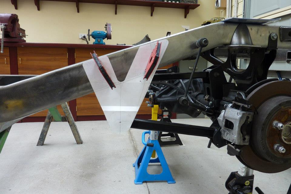
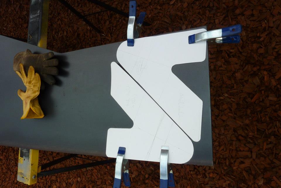
The outside angles of the bracket is set at 22.5*. Very common angle used in engineering and even my house roof is at this pitch. It also worked out that it would cover the upper control arm mount as well. The extra V taken out of the top is for a few reasons. One is that it then makes the weld length on the top and bottom of the rail the same. The top would have been 50% longer otherwise if fully welded and that would have caused the frame to bend upwards after welding. It also allows welds in the middle of the bracket increasing its strength. Lastly it reduces the weight of the bracket both physically and visually. Can also see the fold I will be putting in to accept the extra width the bush has over the frame width. The new brackets from 4mm plate. There is a inner and outer template due to needing extra length for the fold that goes into the outer one. The curved bit at the bottom of the V was first cut out using a hole saw. Then the rest just using a 9" cutoff wheel.
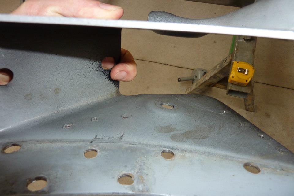
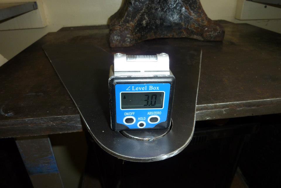
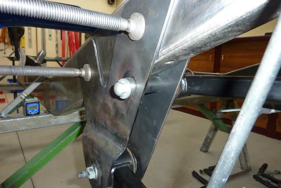
Now the lower arms do not run exactly parallel with the frame but skew outwards by 3*. This is common and helps reduce binding during axle articulation. The way they set the original mounts up was to press the 3* around the mounting hole. I decided to do simulate the factory way by cutting out a 2" disc using a hole saw around the mounting point, tacking it in top and bottom, then tilting it to 3*
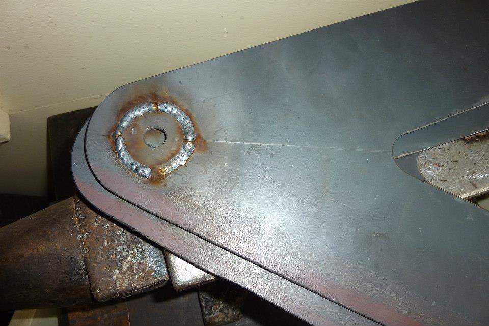
The holesaw thickness left a nice even gap all the way around to get a nice deep weld in from both sides. The lower mount was then clamped up into position to check that the lower control arm ended up at the same angle as I had recorded before pulling the the donor.
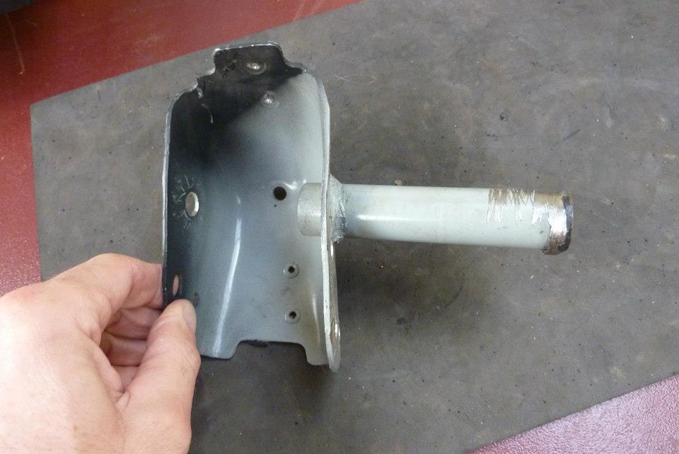

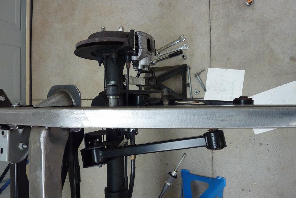
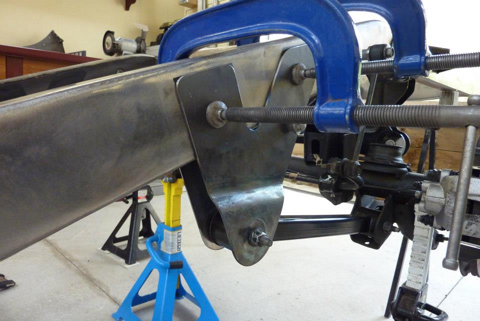
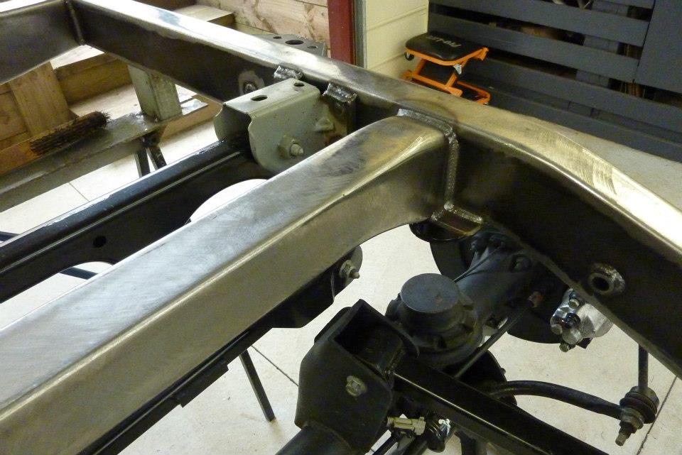
The original upper control arm mount will be used again. The tube passed through the donor frame rail and will have it pass through the upper control arm plates in this case. The upper arms were placed at the donor factory angle and made sure the pinion was at it too matching the transfer case output flange.
Can see how well the upper control arm is supported. Both ends of the arms brackets were plated as well to further strengthen them.
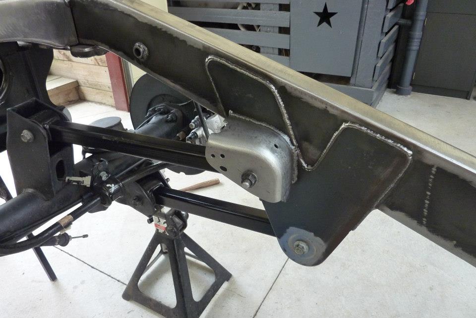
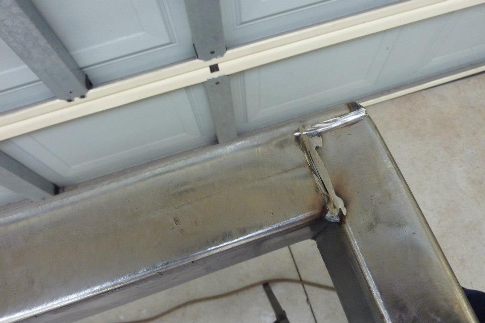
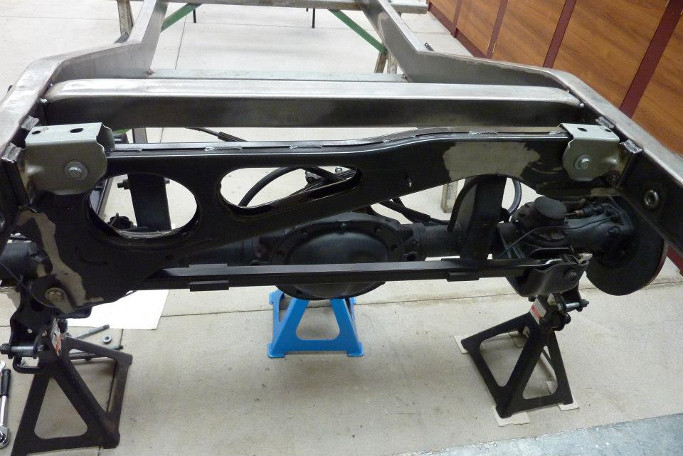
Fully welded the brackets in place. Also ground a V into the join ready for weld on the rear cross member as well to ensure full penetration.
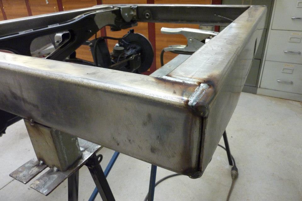
Rear cross member welded in on top and the vertical join needs no further prep before welding. The cross member over the diff was also welded in once bump stops had been fitted and the suspension fully compressed to make sure there was plenty of clearance to the upper control arm axle mounts.
[Index]